Site pages
Current course
Participants
General
MODULE 1. Introduction to mechanics of tillage tools
MODULE 2. Engineering properties of soil, principl...
MODULE 3. Design of tillage tools, principles of s...
MODULE 4. Deign equation, Force analysis
MODULE 5. Application of dimensional analysis in s...
Module 6. Introduction to traction and mechanics, ...
Module 7. Traction model, traction improvement, tr...
Module 8.Soil compaction and plant growth, variabi...
LESSON 19. Traction mechanics
19.1. Traction Mechanics
Fig. 2.1(a) illustrates one of several alternative methods of describing the forces acting on a wheel. The figure is divided into three distinct force states: braked, driven, and driving. The transition point between the braked and driven force states is the towed wheel condition. A towed wheel is unpowered: axle torque is zero neglecting bearing friction. The transition point between the driven and driving force states is the self-propelled wheel condition. For a self-propelled wheel, pull is zero with the applied torque simply overcoming the motion resistance of the wheel.
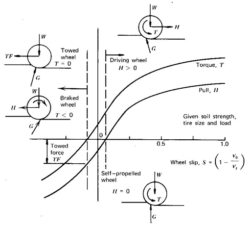
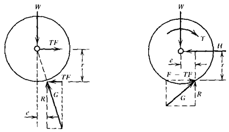
Fig 2.1 (a) Pull- torque slip relation for wheels on soil, (b) Free body diagram of a towed wheel and, (c) Free body diagram of a driving wheel
The curves presented in Fig. 2.1(a) represent a given soil strength, tire size, and load. As soil strength increases, the curves move upward to the left, as soil strength decreases, they move downward to the right.
In Fig. 2.1(a), both the axle torque and pull are plotted as functions of wheel slip. These reactions develop from soil stresses resulting from slippage (motion loss) of the wheel. Slip is defined as
 --------------------------------------------- (2.1)
Where,
S - wheel slip
Va - actual travel speed
Vt - theoretical wheel speed = rw
r - rolling radius of wheel on hard surface
w - angular velocity of wheel
The term "rolling radius" is defined in ASAE S 296.2 (Agricultural Engineers Yearbook 1978) as ‘the distance traveled per revolution of the traction device divided by 2p when operating at the specified zero condition. The zero condition selected here is the vehicle operating in a self-propelled condition on a hard surface, such as a smooth road, with zero drawbar load. This differs from another common zero condition, which is the self-propelled, zero drawbar load condition on the test surface.
The towed force point and driving wheel states are particularly important. Free body diagrams of the wheel for these two conditions are shown in Figs. 2.1(b) and (c).
In Fig. 2.1(b) for the towed wheel, the soil reaction G is resolved into a horizontal component (which from equilibrium considerations must be equal and opposite to the towed force TF exerted at the axle center) and a vertical component R (which must be equal and opposite to the wheel load W). The horizontal component of the soil reaction is assumed to act at a distance r below the wheel center. Note that W includes both the weight of the wheel and any vertical reaction force from the vehicle on which the wheel is mounted. This vertical reaction force will be affected by weight transfer.
Since there is no axle torque acting on the towed wheel,
TFr - Re = 0 --------------------------------------------- (2.2)
or e = (TF/R)r = (TF/W)r. Since ρ = TF/W has been defined as the motion resistance ratio, e = rr.
In Fig.2.1(c) for the driving wheel, the soil reaction G is again resolved into horizontal and vertical components. However, the horizontal component is again assumed to act at a distance r below the wheel center and is now divided into two forces; a gross traction force F and a motion resistance force TF. As the symbol implies, the motion resistance force acting on the driving wheel is considered to be the same as the towed force for the wheel.
Summing forces in the horizontal direction
H = F – TF --------------------------------------------- (2.3)
Defining μg = F/R = F/W as the gross traction coefficient and that μ = H/R = H/W was defined as the net traction coefficient,, dividing equation 6.20 by W gives the relation:
![]() ------------------------------------------- (2.4)
------------------------------------------- (2.4)
Summing the moments acting on the wheel,
T - (F –TF)r -Re = 0 (11)
By using equation 2.2,
T=Fr ------------------------------------------- (2.5)
Thus the wheel torque T is assumed equal to the gross tractive force F acting at a moment arm equal to the rolling radius r.
Last modified: Wednesday, 19 March 2014, 12:44 PM