Site pages
Current course
Participants
General
Module 1 - Water availability and demand and Natio...
Module 2 - Irrigation projects and schemes of India
Module 3 - Concepts and definitions
Module 4 - Command Area Development and Water Mana...
Module 5 - On-Farm-Development works
Module 6 - Water Productivity
Module 7 - Tank & Tube well irrigation
Module 8 - Remote Sensing and GIS in Water Management
Module 9 - Participatory Irrigation Management
Module 10 - Water Pricing & Auditing
LESSON 25. Tank design
25.1 Tank Hydrology
Generally a catchment is classified into one at three categories depending on water absorption characteristics of the soil which are, in turn, dependent on geological formation and slope. Hilly tracks, where run-oft is high are classified as good; catchments with alluvial and red soils where the absorption rate is moderate are designated as average or moderate; catchments with porous sandy soils where the absorption rate is high are designated as poor. For the same amount of rainfall, these three types of catchment will generate quite different levels of runoff.
The water yield or run-off from the rainfall for any given tank is a function of the geographic area and the type of the catchment, i.e., whether the tank is isolated or connected to a group of tanks, or to an adjoining stream or river. Tanks located in the lower reaches of a drainage basin or valley will have the advantage of receiving surplus water from upper tanks, in addition to the run-off from their own catchments areas during the rainy season. The lower tanks do not receive all the run-off from the upper catchment because the upper tanks intercept water. However, a portion of the run-off from the upper catchments usually flows down to the lower tanks. These upper catchments with tanks are designated as intercepted catchments. An empirical assumption has been made that 20 per cent of the run-off from the intercepted catchment flows down to the lower tank.
The water movement depends on the location of the tanks in a tank series or chain. Assume A, B, and C are three tanks in a series. A and B are the upper tanks and C is the lower tank. Area 1 is the tree catchment of tank C, while the areas denoted as 2 and 3 are the free catchments of tanks A and B. The yield for tank C is computed by calculating the total yield of the free catchment in area 1 and adding 20 per cent of the yield from the catchments in areas 2 and 3. Twenty per cent, or 1/5 of the catchment area of an upper tank is known as the “equivalent catchment”. Free catchment (a) + equivalent catchment (b) = combined catchment for a tank.
Another source of water supply for tanks is the diversion of water from a stream or reservoir. This is why it is important to divide tanks into system and non-system tanks. Most system tanks have a greater reliability of supply provided by larger reservoirs. In contrast, non-system tanks are, at best, connected to a stream and receive water whenever there are adequate flows in the stream, usually during the monsoon months. Although rivers or streams help to provide additional water, they do not ensure the reliability of water supply that is afforded by the system tank. The PWD computes the water yield from supply channels based on certain empirical assumptions such as the number of days the supply channel can deliver water to the tank in a year. This may also vary from year to year in accordance with the intensity of rainfall, the number of rainy days, and other catchment characteristics. Generally the PWD assumes a 10 to 15 day supply through the supply channels from rivers or streams in non-system tanks.
In summary, a rainfed-non-system tank or system tank can receive its water from three sources:
(i) its free or independent catchment,
(ii) its intercepted catchment, and
(iii) its supply channels from rivers, streams or reservoirs (if there are any).
The total number of tank fillings is then calculated by dividing the total yield from the three sources by the storage capacity of the tank. For example, if the water yield available for a tank from the above three sources is 20 Mm3, and the storage capacity of the tank is 8.2 Mm3, then the
Number of fillings = Yield/Capacity = 20/8.2 = 2.4
25.2 Tank structural Components
A typical tank irrigation system consists of the following components: surplusing arrangements, feeder canals, tank water spread area, tank bunds, sluices, and distribution system (main canals, field channels).
25.2.1 Disposal of Excess Water
The difference in capacity between the sill level of a sluice and the Full Tank Level (FTL) is the amount of water available to irrigate crops. For tank safety, provisions are necessary to dispose any water in excess of what a tank can safely hold for future use. Structural arrangements designed to serve this function can be categorized as follows: (i) natural ground escape and breaching mechanisms, (ii) surplus weirs, and (iii) calingulah.
In shallow tanks, where the ground level at the flank or at tank ends permits slow drainage, the tank bund can be neatly terraced and gravelled and made hard so that surplus water can be easily drained without scour or erosion. Such an arrangement is known as Natural Ground Escape (NGE). Generally, these types of arrangements are common in small tanks that are located in places where the soil is gravely. This is a cheap and cost effective way of disposing of excess water.
Other types of safety mechanisms require masonry structures to dispose of the excess water. Two types are common: (a) surplus weirs, and (b) calingulah. A masonry weir is constructed for a certain length and height, and should be designed to dispose of any excess water. The length and height of this masonry structure is based on the following factors: (a) amount of rainfall, (b) area of the catchment, and, (c) characteristics of the catchment.
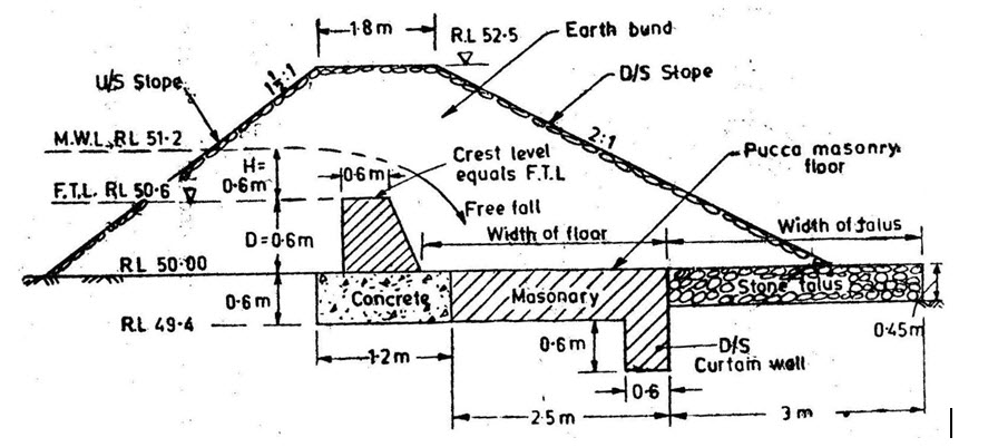
Fig.25.1 Typical dimensions of a surplus weir of a tank with 0.6 m to 0.9 m drop
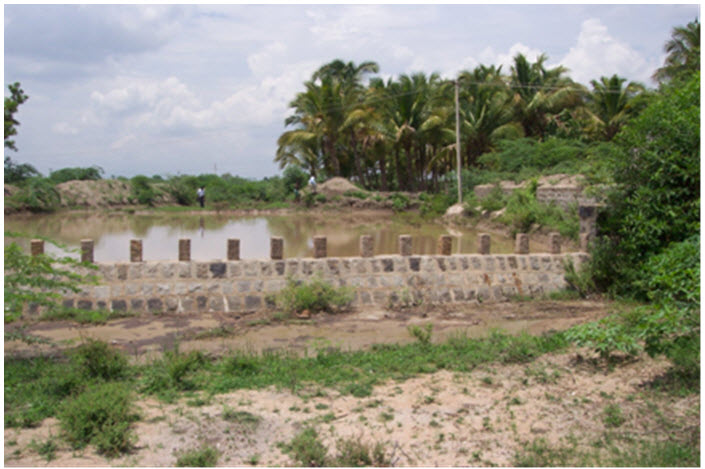
Fig:25.2 Image of Caligulah
The other type of masonry structure is where the crest of the wall is at a lower level than the full tank level. The masonry weir will be embedded with stones up to the Full Tank Level at intervals of 0.3 to 1.8 m (one to six feet). In between the stones, the water level in the tank is maintained with wooden planks or mud. The stones are called calingulah stones and the structure is known as the calingulah type.
This type of structure is normally used in two cases:
(1) In the upper tanks of a chain or group of tanks where such facilities allow a reasonable quantity of water to reach the lower tanks during the rainy season without waiting for the upper tanks to fill. This allows water sharing to occur in a chain of tanks.
(2) In tanks that are very close to mountains or are under the threat of a sudden rush of water from a nearby jungle stream, such an arrangement helps reduce the impact of flood peaks in a tank and helps prevent tank breaches.
While NGE is adopted in small and shallow tanks, surplus weirs and calingulab are adopted for medium and major tanks.
25.2.2. Feeder Canals
These canals come from the catchment areas and usually run only 0.3 km to 3 km in length before joining the water spread area of the tank. In most cases, the Feeder canals have become filled with silt and abandoned. Encroachment and extension of villages due to population pressure and poor maintenance of the canals have also reduced their length and capacity. Abuse of the catchment and supply channels has reduced run-off in many tanks. Over a period of time, this has resulted in lower tank water supplies. Siltation and encroachment have had a more deleterious impact on this is the area where water is stored. For most of the tanks, the ratio of water spread to command area varies from 1:4 to 1:8. For every ha of the water spread, there will be approximately 4 to 8 ha of command area. Since the water supply is erratic, the water spread area will be dry in some years especially in non-system tanks.
25.2.3 Tank Embankment
These earthen bunds or levees are normally in a U shape with greater height at the center and a gradual reduction in height at both of the flanks. The tank bund will be extended so that the water stored in the tank does not escape at the flanks when the tank is full. Depending upon the location normally the bunds are 1 to 3 m wide at the top, facilitating the transport of silt away from the tank by bullock-carts. Heights vary from 1 m to 4 m. The cost of the bund is a major component in tank construction, amounting to about 46 per cent of the total cost. After assessing the location of the phreatic line for the available soil type, core wall of clay or masonry has to be designed to achieve a safe c/s for the earthen bunds. If necessary toe filters are to be provided for embankment safety.
25.2.4 Tank Outlets
In most cases, tank water is drawn by gravity. Depending upon the location of the tank and the topography, the number of sluices varies. Normally the number of sluices ranges from 2 to 4. There are upper and lower sluices, depending upon their capacity to draw water from the tank. Normally the lower sluices are located in the middle or deeper portion of the tank and can draw more water over a longer period of time. The upper sluices, located at a slightly higher level draw water when the water level in the tank is adequate. As the water level drops, the sluices will draw less water and in some cases the sluices do not function since the water level is too low. Sluices at different heights mean that the tank does not allow equity in water supply to all the sluices. As a consequence, there may be mixed crop patterns due to differences in water availability. Water intensive crops are found in the area served by lower sluices while less water intensive crops are found in areas served by the upper level sluices.
25.2.5 Distribution System
The distribution system consists of the main canal, distributaries, and field channels. The main canal generally ranges in length from 0.5 km to 4 km and irrigates from 20 ha to more than 200 ha. The length of canals and the area irrigated varies widely. Distribution networks and their performance depend upon the terrain and the slope of individual command areas. Different designs were adopted depending on what distribution arrangements best suited local conditions. Maintenance of the main canal, distributaries, and field channels is the responsibility of area farmers. In cases where the main channel (due to breaches) is severely damaged, the PWD will assist farmers with repairs. Since the entire distribution system is usually unlined, water losses are high and water is not distributed equitably among head and tail-end farmers. In some cases, the canals are so wide and the drainage conditions so poor, that the excess water reduces crop yields particular in areas near the head of the canals.
25.3 Tank modernisation
Normally the Government has attempted tank rehabilitation through small improvements. However, tank modernization incorporates a much broader range of options to improve tank performance. For tank modernization management changes are considered just as important as physical investments. Tank modernization is the process by which the water in existing tanks is used more efficiently through improved water storage, distribution, and on-farm water use. The aim is to increase food production and rural incomes by achieving higher cropping intensity through improved water management and reduced water losses. The following activities are included under tank modernization:
1. Protecting the tank catchment and storage areas;
2. Improving tank sluices and surplus weirs, and strengthening bunds;
3. Lining main canals and distributaries;
4. Increasing on-farm development activities, including the lining of branch channels and field channels;
5. Establishing tank-level farmer organizations;
6. Adopting improved on-farm irrigation practices;
7. Improving the management of water releases.
Most of the current activities involve rehabilitation below the outlet, while tank modernization includes rehabilitation plus improved water management. To be more effective, tank modernization is needed both above and below the outlets.
25.3.1 EEC tank Modernization Program – Tamil Nadu
This program was implemented during 1984-85 with financial aid from the European Economic Community (EEC). In the first phase (1984-91), a total of 150 non-system tanks with command areas of 100-200 ha were selected for modernization with a financial outlay of Rs 4500 lakhs. In the second phase (1989-1995), an additional 230 tanks (i.e.. 150 tanks with command areas of 100-200 ha and 80 ex-zamin tanks with command areas of 40-50 ha) were included with a financial outlay of Rs 5000 lakhs. The approximate cost per hectare was Rs.21000. The project is expected to save about 20 per cent of water over the present use, thus permitting the expansion of cultivation by about 9000 ha.
To select tanks for modernization, the PWD used the following criteria:
a. the command area of the tanks should be between 100 to 200 ha,
b. the number of tank fillings should be less than two,
c. the command area should be 90-95 per cent cultivated,
d. the tanks should be non-system tanks, and
e. the tanks should be easily accessible.
In addition, groundwater irrigation in tank command areas has gained importance. When wells become highly concentrated the importance of tank irrigation decreases. Hence, it is important to select tanks where tank irrigation remains important and wells are not highly concentrated. Finally, the water supply in system tanks is not necessarily better than supplies in non-system tanks. Not all system tanks get adequate water and many system tanks behave like non-system tanks. Hence, modernization should also be considered for system tanks. The following major concerns should be considered in selecting tanks for modernization:
a) tanks with severe encroachment should be avoided: eliminating encroachers is a socio-political issue. With significant encroachment, modernization is difficult to achieve.
b) tanks with effective water users organizations (WUOs) should be given priority, since WUO can make better use of tank irrigation through simple management techniques.
Once the information about tank selection is communicated from the Chief Engineers office to all the PWD offices, the concerned district Executive Engineer (EE) makes a list of non-system tanks that satisfy the 100-200 ha criterion and submits the list to the District Collector. After the District Collector’s suggestions are incorporated, the EE makes a site inspection and a comprehensive survey incorporating catchment characteristics, command area conditions, and the conditions of tank structures. Hydrological information is collected, normally for a 12-year period. Based on the command area of the tank, cropping patterns, a 75 per cent probability of crop success, and the registered command area, the gap between the area irrigated and the command area is determined. Tanks with larger gaps between irrigated area and command area are given priority. Next, the listed tanks will be surveyed in detail to determine hydrological characteristics, tank breaches, and physical components such as surplus weir, bunds and sluices. In addition, the Agricultural Engineering Department surveys every 10 ha in the command area. Once this is done, the EE will forward the report with a list of tanks to the Superintending Engineer (SE). The SE reviews the report and makes a site inspection. After the SE’s suggestions are incorporated, the report is sent to the Chief Engineer (CE) before going to the Technical Review Committee (TRC) and the Appraisal Committee (AC). Once the TRC and AC approve, the Secretary PWD issues a Government Order (GO). On receipt of the GO, the CE issues a technical and financial sanction to the SE and EE to begin the work.
Last modified: Wednesday, 19 February 2014, 4:15 AM