Site pages
Current course
Participants
General
MODULE 1. Introduction to production of agricultur...
MODULE 2. Advance in material for tractor and agri...
MODULE 3. Advanced manufacturing techniques
MODULE 4. Heat treatment of steel
MODULE 5. Industrial lay out planning and quality ...
MODULE 6. Economics of process
MODULE 7. Techno economic feasibility of project r...
MODULE 8. Servo motors, drives and controllers
MODULE 9. CNC controllers for machine tools
MODULE 10. CNC programming
MODULE 11. Assembly and plant automation storage a...
LESSON 24. INTRODUCTION OF SERVO MOTORS
1.1 Introduction
A servomotor is a rotary actuator that allows for precise control of angular position, velocity and acceleration. It consists of a motor coupled to a sensor for position feedback. It also requires a relatively sophisticated controller, often a dedicated module designed specifically for use with servomotors. Servomotors are used in applications such as robotics, CNC machinery or automated manufacturing.
Mechanism
As the name suggests, a servomotor is a servomechanism. More specifically, it is a closed-loop servomechanism that uses position feedback to control its motion and final position. The input to its control is some signal, either analogue or digital, representing the Position commanded for the output shaft.
The motor is paired with some type of encoder to provide position and speed feedback. In the simplest case, only the position is measured. The measured position of the output is compared to the command position, the external input to the controller. If the output position differs from that required, an error signal is generated which then causes the motor to rotate in either direction, as needed to bring the output shaft to the appropriate position. As the positions approach, the error signal reduces to zero and the motor stops.
The very simplest servomotors use position-only sensing via a potentiometer and bang-bang control of their motor; the motor always rotates at full speed (or is stopped). This type of servomotor is not widely used in industrial motion control, but they form the basis of the simple and cheap servos used for radio-controlled models. More sophisticated servomotors measure both the position and also the speed of the output shaft. They may also control the speed of their motor, rather than always running at full speed. Both of these enhancements, usually in combination with a PID control algorithm, allow the servomotor to be brought to its commanded position more quickly and more precisely, with less overshooting.
Servomotors vs. stepper motors
Servomotors are generally used as a high performance alternative to the stepper motor. Stepper motors have some inherent ability to control position, as they have built-in output steps. This often allows them to be used as an open-loop position control, without any feedback encoder, as their drive signal specifies the number of steps of movement to rotate. This lack of feedback though limits their performance, as the stepper motor can only drive a load that is well within its capacity, otherwise missed steps under load may lead to positioning errors. The encoder and controller of a servomotor are an additional cost, but they optimise the performance of the overall system (for all of speed, power and accuracy) relative to the capacity of the basic motor. With larger systems, where a powerful motor represents an increasing proportion of the system cost, servomotors have the advantage. Many applications, such as laser cutting machines, may be offered in two ranges, the low-priced range using stepper motors and the high-performance range using servomotors.
Encoders
Simple servomotors may use resistive potentiometers as their position encoder. These are only used at the very simplest and cheapest level, and are in close competition with stepper motors. They suffer from wear and electrical noise in the potentiometer track. Although it would be possible to electrically differentiate their position signal to obtain a speed signal, PID controllers that can make use of such a speed signal generally warrant a more precise encoder.
Modern servomotors use optical encoders, either absolute or incremental. Absolute encoders can determine their position at power-on, but are more complicated and expensive. Incremental encoders are simpler, cheaper and work at faster speeds. Incremental systems, like stepper motors, often combine their inherent ability to measure intervals of rotation with a simple zero-position sensor to set their position at start-up.
Many servomotors are rotary, but are used for ultimate control of a linear motion. In some of these cases, a linear encoder is used. These servomotors avoid inaccuracies in the drive train between the motor and linear carriage, but their design is made more complicated as they are no longer a pre-packaged factory-made system
Motors
The type of motor is not critical to a servomotor and different types may be used. At the simplest, brushed permanent magnet DC motors are used, owing to their simplicity and low cost. Small industrial servomotors are typically electronically-commutated brushless motors. For large industrial servomotors, AC induction motors are typically used, often with variable frequency drives to allow control of their speed. For ultimate performance in a compact package, brushless AC motors with permanent magnet fields are used, effectively large versions of Brushless DC electric motors.
Drive modules for servomotors are a standard industrial component. Their design is a branch of power electronics, usually based on a three-phase MOSFET H bridge. These standard modules accept a single direction and pulse count (rotation distance) as input. They may also include over-temperature monitoring, over-torque and stall detection features. As the encoder type, gear head ratio and overall system dynamics are application specific, it is more difficult to produce the overall controller as an off-the-shelf module and so these are often implemented as part of the main controller.
Controllers
Most modern servomotors are designed and supplied around a dedicated controller module from the same manufacturer. Controllers may also be developed around microcontrollers, but this is rarely worth the time and trouble, compared to buying off-the-shelf.
What is the difference between a DC motor and servo motor?
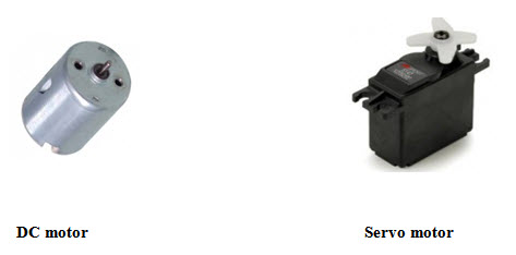
A DC motor has a two wire connection. All drive power is supplied over these two wires. think of a light bulb. When you turn on a DC motor, it just starts spinning round and round. Most DC motors are pretty fast, about 5000 RPM (revolutions per minute).
With the DC motor, its speed (or more accurately, its power level) is controlled using a technique named pulse width modulation, or simply PWM. This is idea of controlling the motor’s power level by strobing the power on and off. The key concept here is duty cycle—the percentage of “on time” versus“off time.” If the power is on only 1/2 of the time, the motor runs with 1/2 the power of its full-on operation.
If you switch the power on and off fast enough, then it just seems like the motor is running weaker—there’s no stuttering. This is what PWM means when referring to DC motors. The Handy Board’s DC motor power drive circuits simply switch on and off, and the motor runs more slowly because it’s only receiving power for 25%, 50%, or some other fractional percentage of the time.
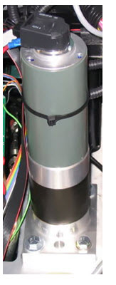
A servo motor is an entirely different story. The servo motor is actually an assembly of four things: a normal DC motor, a gear reduction unit, a position-sensing device (usually a potentiometer—a volume control knob), and a control circuit.
The function of the servo is to receive a control signal that represents a desired output position of the servo shaft, and apply power to its DC motor until its shaft turns to that position. It uses the position-sensing device to determine the rotational position of the shaft, so it knows which way the motor must turn to move the shaft to the commanded position. The shaft typically does not rotate freely round and round like a DC motor, but rather can only turn 200 degrees or so back and forth.
The servo has a 3 wire connection: power, ground, and control. The power source must be constantly applied; the servo has its own drive electronics that draw current from the power lead to drive the motor.
The control signal is pulse width modulated (PWM), but here the duration of the positive-going pulse determines the position of the servo shaft. For instance, a 1.520 millisecond pulse is the center position for a Futaba S148 servo. A longer pulse makes the servo turn to a clockwise-from-center position, and a shorter pulse makes the servo turn to a counter-clockwise-from-center position.
The servo control pulse is repeated every 20 milliseconds. In essence, every 20 milliseconds you are telling the servo, “go here.”
To recap, there are two important differences between the control pulses of the servo motor versus the DC motor. First, on the servo motor, duty cycle (on-time vs. off-time) has no meaning whatsoever—all that matters is the absolute duration of the positive-going pulse, which corresponds to a commanded output position of the servo shaft. Second, the servo has its own power electronics, so very little power flows over the control signal. All power is draw from its power lead, which must be simply hooked up to a high-current source of 5 volts.
Contrast this to the DC motor. On the Handy Board, there are specific motor driver circuits for four DC motors. Remember, a DC motor is like a light bulb; it has no electronics of its own and it requires a large amount of drive current to be supplied to it. This is the function of the L293D chips on the Handy Board, to act as large current switches for operating DC motors.
Plans and software drivers are given to operate two servo motors from the HB. This is done simply by taking spare digital outputs, which are used to generate the precise timing waveform that the servo uses as a control input. Very little current flows over these servo control signals, because the servo has its own internal drive electronics for running its built-in motors.
References:
http://en.wikipedia.org/wiki/Servomotor
http://handyboard.com/hb/faq/hardware-faqs/dc-vs-servo/
Last modified: Friday, 28 March 2014, 6:49 AM