Site pages
Current course
Participants
General
Topic 1
Topic 2
Topic 3
Topic 4
Topic 5
Topic 6
Topic 7
Topic 8
Topic 9
Lesson 3. THE BENCH WORK TOOLS, ITS USES AND PROCESSES
Module 2. Bench work tools and processes
THE BENCH WORK TOOLS, ITS USES AND PROCESSES
3.1 Miscellaneous Tools
1. Punch
A punch made from a steel rod with a length of 90 to 150 mm and a diameter of 8 to 13 mm is used in bench work for marking purpose and locating centres in more permanent manner. The punch with a tapered point angle of 400 is called a princk punch and that of600 point angle is called a centre punch.
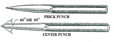
Fig. 3.1 Punch
2. Calipers
Calipers are the devices used for measuring and transferring the inside or outside dimensions of components. Although gradually they are being replaced by the more accurate and precision instruments and gauges, like micrometers in modern workshops, still they stand as the in general work on account of their cheapness and ease in handling.
3. Screw Drivers
It is a very useful hand tool for rotating the screws. It consists of wooden or a plastic handle and steel blade, shaped at the end. The flat end of the tool is inserted into the slot provided on the head of the screw for rotating it. Screw drivers are made in various sizes to suit the corresponding sizes of the slots on the screw heads. Sometimes star headed screw driver is used for star headed screws.

Fig. 3.2 Screw driver
4. Drills
Drilling is an important operation carried out in a fitting shop for producing different types and sizes of holes in various materials. There are many forms of drills used for this purpose.
The simplest form is a flat drill which is used for wood work. The other important and most widely used is a fluted twist drill. It has a cylindrical body carrying the spiral flutes cut on its surface. Twist drills are usually made of high-speed steel, some cheaper varieties are made of high carbon steel. They are made in different forms to suit the work but the most commonly used types are (i) those having parallel shank and (ii) those having tapered shank,Parallel shank is provided on small sized drills (say up to 12.7 mm) only and those above this size are usually provided with a tapered shank.
The twist drill essentially consists of two main parts, a shank which is gripped in the chuck of the drilling machine and the body forms the main cutting unit. Main advantages of using twist drills are:
1. The chips of the metal are automatically driven out of the hole through the spiral flutes.
2. Cutting edges are retained in good condition for a fairly long period.
3. Heavier feeds and speeds can be quite safely employed.
4. For the same size and depth of hole they need less power as compared to other forms of drills.
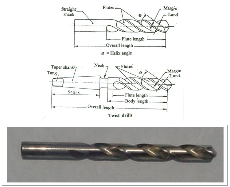
Fig. 3.3 Twist drill
The hand operated taps used in fitting shops are employed for cutting internal threads in cylindrical holes or for cleaning damaged threads in similar parts. A tap consists of a toothed body having flutes (usually 4) cut on its surface, a round shank and a square formation at the end of the shank. The flutes are provided for the same purpose as in case of a twist drill and square formation at the top enables to grip by the tapping handle.
All the hand taps of different sizes are usually available in a set of three taps of each size known as taper or rough, second and finish or plug respectively. The main difference between the three taps is the chamfer angle. In the threading operations they are used in the same order as taper, second and plug.
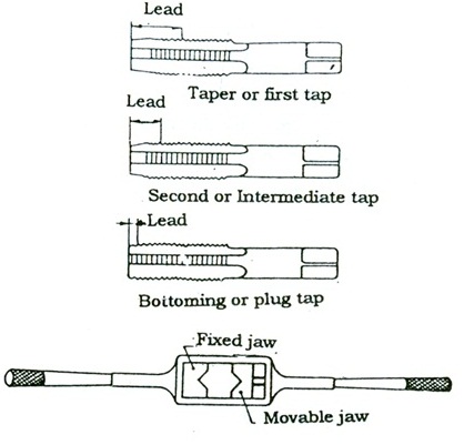
Fig. 3.4 Taps and tap wrench
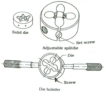
Fig. 3.5 Die and die handles
3.2 Bench Work Processes
Bench work involves following hand operations to finish the work to desired shape and size with required accuracy.
1. Marking
2.Chipping
3.Sawing
4. Filing
5. Draw filing
6.Threading
7. Grinding
Some common bench work processes are described here
1. Marking
- It is the basic and one of the most important operations in bench work.
- It should be remembered that how accurately and carefully one tries to perform other operations it will be of no help until and unless the piece has been properly and accurately marked.
- Sufficient care should be exercised in performing this operation to obtain a desired fitting of the components.
- Marking on the work can be done by setting out dimensions with the help of a working drawing.
- The surface to be marked is coated with either the paste of red lead or chalk and allowed to dry.
- After that, the work is held in a clamp, if it is round. If the work is too thin, it is normally supported against an angle plate keeping the surface to be marked in a vertical plane. Lines in horizontal direction are scribed by means of a scribing gauge.
- Lines at right angles to this can be drawn easily by first turning the work through 90 and then using the scriber.
- Lines can easily be marked with the help of a try square. Circles and arcs on flat surfaces are inscribed by means of dividers.
- After the scribing work is over, indentations on the surface are made, by using the center punch and hammer along the scribed lines and arcs.
- The punch marks serve as the guide during further operations like filing, chipping and drilling. etc.
2. Chipping
- It is the operation employed for removing the excess metal by means of cold chisels.
- To have a properly chipped surface it is essential that the same cutting angle should be maintained throughout the operation.
- In case the surface is too large it is advisable to cut grooves along the whole surface by means of a cross cut chisel and then chip off the remaining metal.
- The cutting angles of the chisels differ for different metals.
- Frequent lubrication and cooling of the cutting edge, while taking heavy cuts for removing large amount of metal, it helps considerably in chipping the metal easily and more effectively.
- To the correct cutting angle of the chisel, proper gripping of the chisel and the hammer and correct standing position of the operator play a significant part.
- The chisel should be firmly gripped in one hand leaving about 3 to 5 cm length above the thumb of the hand, and hammer should be held near the end of the handle to ensure more power in the blows.
- The operator should stand erect with his two feet sufficiently apart to balance his own weight equally on both the feet.
- The operator should always see the cutting edge of the chisel and not the top of the same.
3. Sawing
- This operation is performed in fitting shop for cutting different metal pieces to the desired size and shape, usually prior to other operations such as filing, drilling, scraping, etc.
- It is also employed for cutting metal pieces of required length out of the bar stock.
- For sawing, the saw blade should be properly fitted, and stretched to have the proper tension, in such a way that the cutting teeth always point away from the operator so as to cut the metal in forward stroke.
- Sawing should be done steadily and slowly.
- An average speed of about 50 strokes per minute is a good practice.
- Sufficient pressure should be exerted in the forward stroke and this be relieved during the backward stroke.
- It is advisable to use a coolant throughout the operation. A new blade should not be directly used on a hard metal.
4. Filing
- Similar to the saw blades, most of the files have their teeth pointing away from the operator such that they cut during the forward stroke.
- The pressure of the hand in filing should also be applied only during the forward stroke and relieved during the return stroke.
- Beginners particularly should be careful enough to practice correct movement of file.
- It should always be more in a perfect horizontal plane for obtaining a truly plane and smooth surface.
- As far as possible, try to use full length of the file during the operation.
- Moving the file diagonally on a flat surface always yields best results. A coarse pitched file should be employed when enough metal is to be removed, followed by finishing with a smooth file.
5. Draw filing
- When the surface is to be finally finished by filing only and no other operation, like scraping, is to follow the filing operation, a special method of filing, called Draw filing, is employed for finishing the surface.
- A flat file of fine cut is used for this operation.
- It should be ensured before use that the file teeth are free from metal particles,
- Other wise a numbers of scratches will be produced on the surface. It is usual to employ a file card quite frequently for cleaning the file teeth both before use as well as during use.
- For draw filing operation the file is held flat on the surface between the two hands.
- The file must move forward and backward. Flatness and evenness of the surface should be checked quite frequently during the operation.
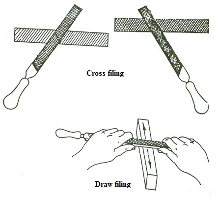
Fig. 3.6 Cross and draw filing