Site pages
Current course
Participants
General
Topic 1
Topic 2
Topic 3
Topic 4
Topic 5
Topic 6
Topic 7
Topic 8
Topic 9
Lesson 8. ELECTRIC ARC WELDING
Module 5. Welding
ELECTRIC ARC WELDING
8.1 Introduction
Welding is process of joining similar metals by application of heat with or without application of pressure and addition of filler material. Such a welded joint has continuous homogeneous material of the similar composition and properties of the parts being joined together. All the engineering branches and metal industries extensively make use of welding processes in one or other form.
8.1.1 Types of welding
Welding methods may be broadly classified in two general groups.
I. Plastic welding: It is also known as pressure welding. Metal pieces to be joined are heated to a plastic state and then forged together by external pressure generally without addition of filter material.
a) Forge welding : heating by a forge
b) Resistance welding : heating by electrical resistance
c) Thermit welding : heating by chemical reaction (without filler metal)
II. Fusion welding : It is also known as non-pressure welding. Material at the joint along with the filler metal, is heated to a molten state and allowed to solidified. Filler metal is used.
a) Arc welding : Heating by electrical arc.
b) Gas welding : Heating by gases.
c) Thermit welding : Heating by chemical reaction & with filer metal.
Apart from the above processes,solid state welding, newer welding etc are also the newly developed welding processes.
8.1.2 Electric arc welding
An electric arc is produced when two current carrying conductors are brought together and then separated by small distance provided there is sufficient voltage available to force a flow of current through the air gap. The arc produced is associated with a bright glow and intense heat throughout its length and may have a temperature of the order of about 5000oC to 5500oC. An arc is produced between a work piece and a carbon electrode at a voltage of about 35 to 40 volts and that between a work piece and a metal electrode at about 15 to 40 volts. Since most of the commercial circuits, normally operate at much higher voltages it is necessary to use specially designed equipment for producing arc for welding.
An arc suitable for welding may be struck in any one of the following ways.
- Between consumable metal electrode and the work piece.
- Between a non-consumable electrode and the work piece.
- Between two non-consumable electrodes.
- Between two work pieces.
An arc between a consumable filler metal electrode and the workpiece is extensively used in many of the welding processes today. When the arc is of the intense heat produced, quickly melts the work piece metal under the arc and produces a molten metal. Simultaneously the end of the electrode melts and the molten metal is carried by the arc into the metal pool on the workpiece to provide a filler to the joint. A proper arc length is important for sustaining the arc and producing a good weld. The processes which use an arc produced between a consumable electrode and the work piece include metal arc welding.
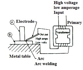
Fig. 8.1 Electric arc welding
Arc welding equipment:
1. AC or DC machine 2. Electrode
3. Electrode holder 4. Cables, cable connections
5. Chipping hammer 6. Earthing clamps
7. Wire brush 8. Helmet
9. Safety goggles 10. Hand gloves
8.3 AC or DC Machine
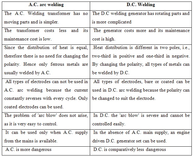
An arc suitable for welding can be either with AC or DC source. The voltage ranges from 15 to 45 volts depending on the welding process. The current for welding may range from 30 to 600 amperes depending on the process and the thickness of material to be welded.
Ordinary electrical loads like heaters and motors work with, steady voltage and current but the welding arc is highly unsteady in both these parameters. The nature of the welding process itself results in frequent short circuits.
It is filler metal in the form of a wire or rod used as a terminal in an electric current for the purpose of producing an electric arc. The electrodes are classified as consumable electrode and non-consumable electrode.A consumable electrode is similar in composition to the metal being welded and it melts to become a part of weld.
Anon-consumable electrode may be made of carbon, graphite or tungsten, which do not consume during the welding operation. When the core of the bare metallic wire is provided with a covering or coating of some fluxing materials it is known as coated electrode. The slag forming constituents are silicate;manganese oxide and iron oxide are used for coating. The advantages are to facilitate the establishment and maintenance of arc, to protect the molten metal from the oxygen and nitrogen of the air by producing a shield of gas around the arc and welding pool, to provide the formation of a slag so as to protect the welding seam from rapid cooling and to provide a means of introducing alloying elements. The coated electrode may be light coated or heavy coated. Both bare and coated electrods for hand arc welding are made up to 12mm in diameter and 450mm long.
8.5 Chipping Hammer
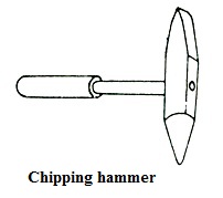
Fig. 8.2 Chipping hammer
Wire brush is a cleaning tool. It is used for removing loose slag,spatter and oxides.
8.7 Helmet
A helmet is used by the welder for protection of his eyes, face and the throat from harmful rays of electric arc and from the hot flying particles or spatter.
8.8 Hand Gloves
For protection of wrist and hands, gloves are worn by the welders.They are made of leather or asbestos. They should be as flexible as possible.Gloves provide protection against.
8.9 Types of Welded Joints
The common joints used in forge welding may be lap joint, butt joint, T joint and V joint. The relative positions of the two pieces being joined determine the type of joint.The following are the five basic types of joints commonly used in fusion welding.
8.9.1 Lap joint
This is used to joint two overlapping plates so that the edge of each plate is welded in the other. The lap joint is obtained by over lapping the plates and then welding the edges of the plates. These joints are employed on plates having thickness less than 3 mm.
8.9.2 Corner joint
It is used to joint two edges of two plates whose surfaces are at right angles to each other. The corner joint is obtained by joining the edges of two plates whose surfaces are at an angle of approximately 90 ° to each other. It is used for both light and heavy gauge sheet metal.In some cases corner joint can be welded, without any filler metal, by melting off the edges of the parent metal.
8.9.3 Butt joint
The butt joint is obtained by welding the ends or edges of the two plates, which are approximately in the same plane with each other. In butt welds, the plate edges do not require beveling if the thickness of plate is less than 5 mm. On the other hand, if the plate thickness is 5 mm to 12.5 mm,the edges should be beveled to V or U-groove and plates having thickness above12.5 mm should have a V or U-groove on both sides
8.9.4 T-joint
The T-joint is obtained by joining two plates whose surfaces are approximately at right angles to each other. It is widely used to weld stiffeners in aircraft and other thin walled structures. These joints are suitable up to 3 mm thickness.
It consists of joining the edge of parallel plate by means of weld. The edge joint is obtained by joining two parallel plates. It is economical for plates having thickness less than 6 mm. This joint is unsuitable for members subjected to direct tension or bending.
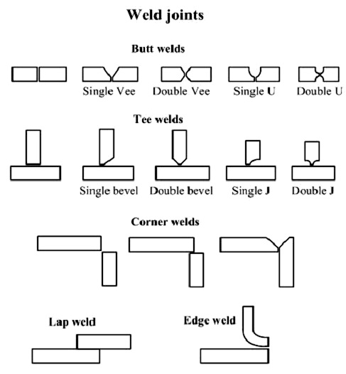
Fig. 8.3 Types of welded joint
8.10 Welding Positions
The welding positions are classified as follows:
8.11 Flat position (F)
In this position, the filler metal is deposited from the upper side of the joint with the face of the weld horizontal.
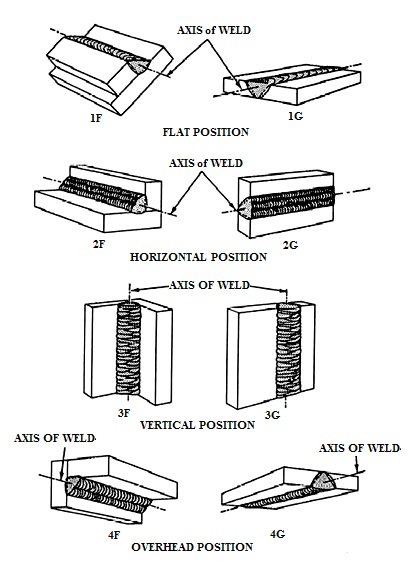
Fig. 8.4 Welding position
In this position, the weld is deposited upon the side of a horizontal and against a vertical surface.
8.13 Vertical Position(V)
In this position, the line of welding is in a vertical plane and the weld is deposited upon a vertical surface.
8.14 Overhead Position(O)
In this position, the weld is deposited from the under side of the joint and the face of the weld is horizontal. It is the reverse of flat welding.
8.15 Resistance Welding
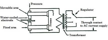
Fig. 8.5 The electric circuit of a resistance welder
Resistance welding which is used with sheet metal from 0.5 to 3.2mm thick and with steelpipe tubing is employed mainly for mass production. Metals of medium and highresistance such as steel, stainless steel, monel metal, silicon bronze etc areeasy to weld. The resistance welding can be subdivided in number of processesbut the important are :
1) Butt
2) Spot
3) Seam
4) Projection