Site pages
Current course
Participants
General
Topic 1
Topic 2
Topic 3
Topic 4
Topic 5
Topic 6
Topic 7
Topic 8
Topic 9
Lesson 13. INTRODUCTION TO SHAPER AND PLANER MACHINE, CNC MACHINES
INTRODUCTION TO SHAPER AND PLANER MACHINE, CNC MACHINES
13.1 Introduction
A shaper is a machine tool that uses reciprocating straight line motion of the tool and a perpendicular feed of the job or the tool. By moving the work piece across the path of the reciprocating tool a flat surface is generated regardless of the shape of the tool. With special tools, attachments and devices for holding the work, a shaper can also be used to cut external and internal key ways, gears, racks, dovetails, T-slots and other miscellaneous shapes.
Shaping is essentially an inefficient method of metal removal but the simplicity of the process coupled with short set up time and cheap tooling makes it extremely useful for single job.
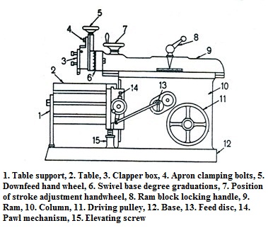
The most common type of horizontal shapers is the production push cut shaper. This type of shaper consists of a frame or column supported on abase, a reciprocating ram and a work table. The frame houses the drive mechanism of the shaper. The top of the frame provides guide ways for the ram.The front of the frame provides guide ways for a cross rail which can be moved up and down. Sliding along the cross rail, perpendicular to the line of motion of the ram is a saddle which carries the work table. On the front end of the ram is fitted a tool head which holds the tool and is provided with means for feeding the tool into the work.
The reciprocating motion of the ram provides the straight line motion to the tool which is the speed for cutting. The vertical movement of the cross rail permits jobs of different heights to be accommodated below the tool and is a machine setting. Motion of the table along the cross rail provides the feed motion for horizontal shaping. The motion of the tool slide on the tool head in conjunction with the swivel base provides feed motion for vertical and angular cuts. The motion of the table along the cross rail for feeding is powered by a paul and ratchet arrangement and timed by actuating the paul by the shaper ram drive the feed is provided at the end of return stroke.
The tool slide swivel base is held on the circular seat on the ram and is graduated to indicate the angle of swivel. The apron consisting of the clapper box, the clapper block and the tool post is clamped on the vertical slide by a screw. It can be swivelled about the apron swivelp in by releasing the clamping screw. The clapper block which carries the tool post is connected to the clapper box by means of a hinge pin. The clapper box-blocks assembly provides a rigid support to the tool in the forward or cutting stroke but on the return stroke the clapper block is lifted out of the clapper box to clear the tool from the work piece. This prevents scratching of the work piece and wear of the tool due to tool dragging.
13.2 Shaper Mechanism
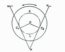
In a shaper rotary movement of the drive is converted into reciprocating movement by the mechanism contained within the column or frame of the machine. The ram holding the tool gets the reciprocating movement. In a standard shaper metal is removed in the forward cutting stroke, while the return stroke goes idle and no metal is removed during this period. This mechanism is known as quick return mechanism. The reciprocating movement of the ram and quick return mechanism of the machine usually obtained by any one of the following methods:
2. Whitworth quick return mechanism
3. Hydraulic shaper mechanism
The angular velocity of the crank pin being constant the return stroke is, therefore, completed within a shorter time for which it is known as quick return motion.
Cutting time to return time ration usually varies between 2:1 and the practical limit is 2:2.

Fig. 13.1 Principle of quick return

Fig. 13.2 Parts of a standard shaper
The planer is almost exactly similar to a shaper, and is primarily intended to produce plane and flat surfaces by a single point cutting tool. The fundamental difference between a shaper and planer is that the table reciprocates past the stationary cutting tool and feed is supplied by the lateral movement of the tool, where as in a shaper the tool reciprocates and the feed is given by the crosswise movement of the table.
Longer stroke of practically unlimited length can be obtained by having the work piece attached to a long, horizontal, reciprocating bed while the tool is attached to a massive column or arch or, rather, a cross-rail with a lead screw that generates the feed movement.
Most planer cut in one; some, in both directions. The slots and holes are provided for bolts,keys, pins for holding and locating work pieces on the finished table top.
The large work that is not expected to be machines on other machines, such as shapers is conveniently machined on planners.
13.4 Slotter
The slotter machine operates almost on the same principle as that of a shaper. The major difference between a slotter and shaper is that in a slotter the ram holding the tool reciprocates in a vertical axis, whereas in a shaper the ram holding the tool reciprocates in a horizontal axis. A slotter is therefore, considered a vertical shaper, and they are almost similar to each other as regards their construction, operation, and use.
The slotter is used for cutting grooves, key ways, and slots of various shapes, for making both internal and external regular and irregular surfaces.
13.5 NC-CNC Machine Tools
Numerical control or computerised numerical control is a technique of automatically operating a productive facility based on code of letters, numbers and special characters. The complete set of coded instructions; responsible for executing an operation is called part programme. In computer-aided part programming, much of the tedious computational work needed in manual programming is performed by the computer microprocessor. This programme is translated into electrical signals to drive various motors to operate the machine to carry out the required operations. Avoidance of human intervention, omission of conventional tooling and fixturing and quick change capability of NC system are the primary factors considered to decide the level of acceptance of machine tools for a particular job. All NC/CNC machine tools are provided with drive motors and other accessories to do auxiliary functions of the machine along with the work table, spindle and other hardware of the traditional machine tools.