Lesson 16. USE OF JIGS AND FIXTURES IN PRODUCTION
Lesson 16
USE OF JIGS AND FIXTURES IN PRODUCTION
16.1 Jigs and Fixtures
l. Jigs and Fixtures are Production-work holding devices used to manufacture duplicate parts accurately. A Jig is a special device that not only holds the work piece but also guides the cutting tool as the operation is performed. It is a special device that has built in features for automatically determining location dimensions for machining or assembly. A jig can assist in guiding tools and clamp the work piece.
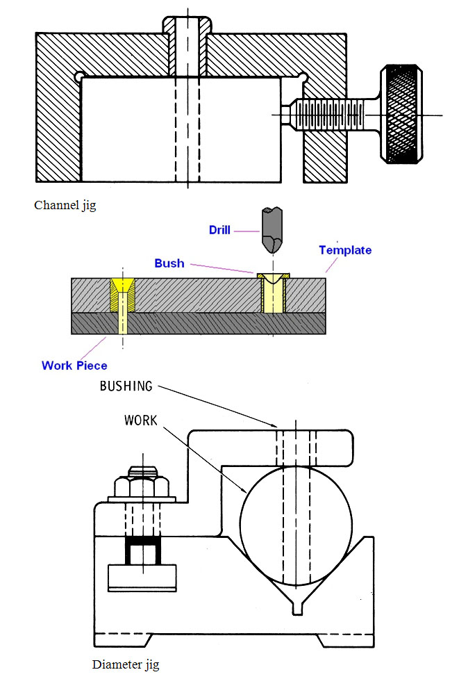
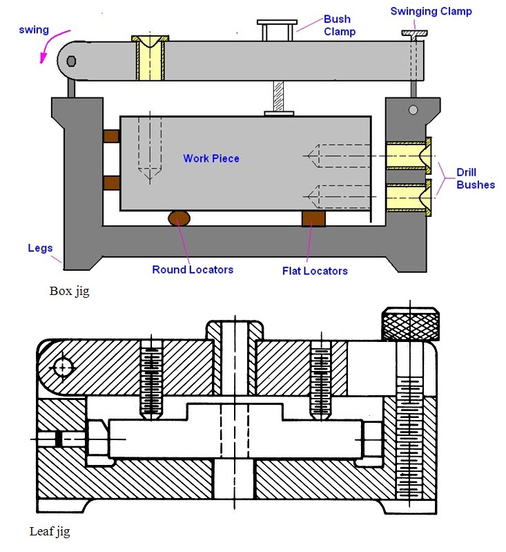
Various types of jigs are: Plate, Diameter, Channel, Leaf, Ring, Box etc.
2. A Fixture is a production tool that locates , holds and supports the work securely so that the required machining operations can be performed. A device which clamps work during machining. Usually designed for a specific part or family of parts. The primary purpose of a fixture is to clamp the work piece.
The application of jigs and fixtures is an important aspect of workshop engineering, and their application is of some consideration on all but the simplest types of production, small orders and tool room work.
16.2 Elements of Jigs and Fixtures
- Locating Elements: These position the work piece accurately with respect to the tool guiding or setting elements in the fixture.
- Clamping Elements: These hold the work piece securely in the located position during operation.
- Tool Guiding and Setting Elements: These aid guiding of the tool in the correct position with respect to work piece.
16.3 Advantages of Jigs and Fixtures
2. Interchangeability
3. Skill Reduction
4. Cost Reduction
2. Study of the type of the capacity of the m/c.
3. Study of the locating elements.
4. Study of the clamping arrangement.
5. Study of clearance between jig and the component.
6. Study of the indexing devices.
7. Study of the fool-proofing arrangement.
8. Study of the ejecting devices.
9. Study of the swarf removal arrangement.
10. Study of rigidity and the vibration problems.
11. Study the safety devices.
12. Study the methods of manufacture of jigs and fixture.
The primary object of their use might be
- to facilitate the holding and support of an awkward or frail article for some machining operation,
- to position a component and guide the cutters so that every component will be uniform,
- to accommodate several components at one setting to take advantage of multiple machining,
- to hold a component which could not be held conveniently without a fixture, and so on. Probably the use of a jig would achieve more than one of the above objects and others we have not mentioned but which will emerge in our subsequent discussion.
16.5 Types of Jigs

Fig. 16.1 Channel & diameter jig

Fig. 16.2 Box & leaf jig
Correct location influences the accuracy of the finished result, and particularly its positional relationship with other surfaces on the component. An important aspect of design is concerned with the location of the component. Furthermore, unless location arrangements are reliable and consistent, the jig will not produce uniform components. Location arrangements are closely related to other aspects of jig application; for example, a perfectly satisfactory method of location might be spoiled by faulty methods of clamping causing the component to lift away from the locating face, or due to poor design a locating face might be clogged by swarf.
16.5.2 Methods of location
16.5.2.1 Locating plugs
- According to the conditions of application, a plug may be fixed as a permanent part of the construction or it may be loose. Unless the job is of a very simple nature for use with only a few components, locating plugs should be hardened and ground, a case-hardening steel being suitable as the soft core lends toughness. When the plug is a permanent part of the jig, it may be a drive fit into a bored hole or it may be secured by a nut and washer.
- Locating plugs should not, in general, be screwed in to a jig, as it is impossible to guarantee the locational accuracy of a screwed connection. If such an arrangement is unavoidable, a plain pilot portion jig-bored to position will help to secure accuracy, but even this is far from ideal. When loose plugs fit into the jig, a hardened and ground bush should be provided as otherwise it will be necessary, sooner or later, to overcome the wear by reboring the hole and fitting a bush.
- o When a component locates on two plugs, one provides all the location necessary except the angular radial position of the second hole. The important hole, therefore, should have a full plug, and the other plug may be cut away, to facilitate insertion of the component and compensate for small variations in centre distance of the holes.
- Detachable plugs should be as light as possible and provided with generous handles or permanent tommy bars if they are to escape mutilation by hammers or spanners. Lightness may be obtained by making plugs hollow. To facilitate their insertion, plugs should be provided with a gradual lead and a radius on the end .It should never be necessary to employ more than two plugs to locate a single, rigid component.
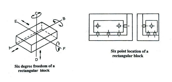
As shown in Fig, a rectangular block is free to move along the axis AB, CD and EF. The body can also rotate about these axis, and thus the total degrees of freedom of a body along which it can move a jig, all these six movements must be restrained by arranging suitable locating points and then clamping the block in position. The principles of determining locating points are as under:

It is assumed the blocked shown in the figure is made to rest on several points on the jig body as shown. The bottom of the block is supported against three points, the rear face of the block bears against two points and the side of the block rests against a single point all projecting from the jig body. It will be now clear that the downward movement of the block along CD is restrained by three supporting points, which have the capability of supporting even a rough casting. The movement along EF and AB axis are restrained by the double and the single points respectively. The rotary movement of the block about AB, CD and EF are also restrained by the bottom, back and side pins. The six points thus serve to locate a block correctly while restraining all its movements. The locating points for an uneven object can be determined by different arrangements, but the guiding principle remains the same.
16.5.3 Clamping
In all forms of jigs and fixtures it is necessary to provide facilities for clamping the work, and there are several important aspects to this.
- Work should be held rigidly to the jig, and to locating faces, but should not be distorted in any way. This involves the use of efficient clamping methods, applied at points where they will act against solid metal, with the avoidance of forces directed where there is no support. Thin, fragile components require particular consideration if distortion is to be avoided.
- Clamping should be simple, quick and foolproof. Jigs are often used by unskilled operatives who do not possess the mechanical instincts necessary to tighten clamps intelligently. Generous allowance must be made for this in the design of clamping arrangements.
- The components of the clamping system must be robust, and as far as possible made non-detachable. The first point is obvious, but cases are often seen where clamps are too thin for the forces put on then and become bent in consequence. Detachable parts of jigs often get mislaid.