Site pages
Current course
Participants
General
Module 1: Watershed Management – Problems and Pros...
Module 2: Land Capability and Watershed Based Land...
Module 3: Watershed Characteristics: Physical and ...
Module 4: Hydrologic Data for Watershed Planning
Module 5: Watershed Delineation and Prioritization
Module 6: Water Yield Assessment and Measurement
Module 7: Hydrologic and Hydraulic Design of Water...
Module 8: Soil Erosion and its Control Measures
Module 9: Sediment Yield Estimation/Measurement fr...
Module 10: Rainwater Conservation Technologies and...
Module 11: Water Budgeting in a Watershed
Module 12: Effect of Cropping System, Land Managem...
Module 13: People’s Participation in Watershed Man...
Module 14: Monitoring & Evaluation of Watershe...
Module 15: Planning and Formulation of Project Pro...
Module 16: Optimal Land Use Models
Keywords
Lesson 15 Problem /Types of Water Induced Soil Erosion & Measures for its Control
15.1 Problem of Water Induced Soil Erosion
Detachment of soil from its original location and transportation to a new location is known as soil erosion. Mainly water is responsible for this erosion although in many locations wind, glaciers etc. are also the agents causing soil erosion. Unless otherwise stated, erosion will refer to only water erosion in this lesson. The natural erosion under a balanced condition of forest and vegetative cover is responsible for the creation of earth’s crust over millions of years. Weathered and disintegrated rocks mixed with decomposed organic matter got deposited on the surface during this slow process of soil formation. This top soil surface supports all the plant life and consequently animal and human life also. With the beginning of human civilization, harmful soil erosion process started. Man felled trees to create land for farming, construction of houses, roads etc. The soil was tilled in any manner for farming and any type of crop was grown anywhere. Coupled with this, overgrazing by animals created favourable conditions for soil erosion. By the time man could realize this ill effect, it was too late and required very expensive protection measures.
History of Soil Erosion
Although man could realize the ill effects of erosion much later, he has been unconsciously struggling with the problem since farming started. Man constructed bunds around the cropped plots to conserve water and soil. Farming started about 7000 years ago when man began to settle and leave nomadic life. It is reported that the first civilization started in the plains of Mesopotamia located in the valley of Tigris and Euphrates rivers. It gradually developed into the world’s best civilization during the time of the Babylonians, Assyrians etc. The downfall of this civilization can be attributed more to the unwise utilization of the fertile land resources rather than the successive invasion by different regimes.
The Nile Valley consisting of Egypt, Uganda, Sudan and Ethiopia are also considered to be an area of the oldest civilizations of the world. Egypt is called the gift of River Nile. The neighbouring countries of Israel, Syria, Jordan, Greece, Turkey etc. were equally prosperous once upon a time. The rainfall being scanty, farmers started irrigation of the crops through canals. Scientific design of canals was unknown to the man and silting started soon. Mesopotamia has been known as the place of the Garden of Eden and the Tower of Babel. There were high density of population and big cities. This land has seen the rise and fall of at least eleven empires. The debris caused due to erosion for centuries left a deep blanket over these big cities and now the ruins of the cities, some scattered villages can be seen here.
Tigris and Euphrates rivers originate from the mountains that have been made devoid of tree cover by felling and flow through overgrazed hill lands. Runoff water that flew from the catchment into these rivers carried huge silt with it. The silt was deposited in the canal below and it was a difficult task to maintain the canal system. With the growth in population, the canal system was further expanded and maintenance became more difficult. Also there has been repeated invasion of the country and it became almost impossible to fight the invaders and to maintain the canals. As a result the canal system and finally the agriculture failed. With a small agricultural production, only a small population could be supported and the great civilization disappeared.
There are innumerable examples of how soil erosion destroyed civilizations. The Jordan River washed off most of the fertile soils from the slopes and bed rocks can be seen there. High lands of Judea have been severely eroded and a very poor yield obtained. The famous Nabatean civilization of about 2000 years ago along with its capital Petra is in ruins now. This can also be attributed to the breakdown of agriculture system due to severe soil erosion. Shanxi, a province of China faced severe soil erosion after the denudation of forests. Many cultivated areas have turned into gullies.
Classic examples of disappearance of human civilization in India due to the mismanagement of soil resources are Mohenjo-Daro and Harappa. Vast tracts of hilly areas of north eastern states have been made barren by jhuming (i.e., shifting cultivation). Siwalik range of the Himalayas suffered a severe soil loss due to denudation and overgrazing by cattle. The eroded soil silted up the river beds. The Kosi River originating from Nepal got silted up due to erosion problems in the upper catchment. Most of the years, it inundates vast areas in North Bihar. River Damodar has been a river of sorrow for the alluvial plains of West Bengal due to erosion problems in Chota Nagpur region of Jharkhand. Again, by construction of reservoirs and treatment of the upper catchment the problem has been largely overcome.
15.2 Types of Water Induced Soil Erosion
Soil erosion is broadly classified into natural type called geological erosion and manmade type called accelerated erosion. Geological erosion takes place under natural undisturbed conditions when a balance is maintained between the soil, climate and vegetative cover. It is a very slow process and responsible for soil formation as well as soil loss. Both together maintain a balance for favourable growth of the plants. Most of the present topographical features of the world such as natural channels, valleys, canyons etc. are results of the geological erosion. As far, as agricultural lands are concerned, geological erosion is not of much consequence.
Different activities of man such as cutting of forest, felling of trees, cultivation of land, overgrazing etc. have disturbed the natural balance between the soil, climate and vegetative cover. Under this condition, soil erosion is taking place at a much faster rate and this is called accelerated erosion. It. is destructive in nature and caused much land degradation. Only accelerated erosion is a matter of concern for the agricultural land and henceforth it will be referred to erosion only. The erosion can be classified as: (i) water erosion, (ii) wind erosion, (iii) coastal erosion.
Depending upon the degree of erosion and its location, water erosion is further classified as: (a) raindrop erosion, (b) sheet erosion, (c) rill erosion, (d) gully erosion, (e) stream channel erosion. These are discussed in details in the subsequent sections.
Raindrop Erosion
Raindrop erosion is the result of direct impact of raindrops on bare soil or in thin film of water. If the soil surface is covered with good vegetation, much harmful effects do not occur as the drops break into finer sprays and much of it infiltrates into the ground. However, if the raindrop strikes the bare soil, considerable raindrop erosion takes place. The raindrops sometimes fall at high speed of 50 kmph and the soil particles may be splashed to a height of 60 cm and move laterally to a distance of 150 cm.
The same soil particles are generally splashed more than once. Thus they are detached from the main soil body and easily carried with the runoff water. In a level surface much serious problem may not occur as the soil is just shifted from one place to another. But in sloping lands they are easily transported down the slope and may join a rill or a gully from where further downward movement becomes easier. Apart from soil particles, the plant nutrients are also removed and transported from the productive land.
A part of the rainfall with clay and silt suspension infiltrates into the ground. In this process the fine particles are removed due to sedimentation phenomena. These fine particles block the soil pores and the infiltration capacity of the soil is greatly reduced. As a result, the runoff rate increases and more soil particles are transported. Thus raindrops striking bare soils on sloping ground, causes severe damage which intensifies as the duration increases.
Factors affecting raindrop erosion are (i) vegetative cover and mulches, (ii) rainfall, (iii) wind velocity and direction, (iv) soil texture and structure, (v) topography, particularly degree and length of slope. Raindrops falling on plants, crop residue or other mulches lose their energy before striking the soil. High wind velocity in the direction of slope causes higher splash. The wind velocity and air resistance also affects the raindrop velocity. The raindrop velocity depends upon the height of fall up to a height of about 10.5 m after which it attains the terminal velocity. Soil loss increases with the increase of this terminal velocity which may vary from 4.5 to 9 m/s depending upon the drop size. Surface roughness and obstructions reduce the soil loss due to splashing.
Sheet Erosion
Sheet erosion has been defined as the uniform removal of soil in thin layers from sloping land which results from sheet or overland flow occurring in thin layers. The top fertile layer of the soil is slowly skimmed off every year and it flows down as muddy water. The field appears to be the same as it was before the rainy season. But huge amount of soil gets lost every year. Initially the reduction in the crop yield may not be significant. But over the years the yield declines till it reaches a minimum. Sometimes, the lower layers of soil and finally the bed rock may be exposed rendering the soil unfit for any crop production. Therefore, although sheet erosion occurs slowly but it is very harmful as it cannot be detected easily in the initial stage.
Recent studies on the mechanisms of erosion using remote sensing and other photographic techniques indicate that the type of sheet erosion mentioned above rarely occurs. Along with the detachment and transport of soil particles, the second phase of erosion called rill erosion also takes place. High speed photographs clearly indicate the change of position of the microscopic rills. In case loose topsoil is located above a comparatively light subsoil, combination of sheet and rill erosion easily occurs. For a given soil surface with a fixed size, shape and density of soil particles, the eroding and transporting power of sheet flow is greatly influenced by the depth and velocity of runoff.
Rill Erosion
Rill erosion is called the second erosion in which the removal of soil by rain water from small but well demarcated semi-permanent channels or streamlets takes place due to overland flow. Rill erosion starts simultaneously with sheet erosion. But conventionally rill erosion is said to have started when channels are large enough to be visible.
Like sheet erosion, rill erosion is also often overlooked although detachability and transportability of soil are much higher due to higher surface velocity. If care is taken, channels formed due to rill erosion can easily be smoothed out by farming operations. If proper care is not taken, rill develops both in depth and width. Ultimately movement of small farm implements becomes difficult and cropped area reduces. Finally the rills may develop into gullies.
Gully Erosion
If the rills are not attended for a long time they develop further in their depths and widths and finally form gullies. Gullies are therefore an advanced stage of rill erosion, which is an advanced stage of sheet erosion. Once the gully has been formed, it cannot be smoothed out by normal cultivation practices. It requires costly and effective structures/ practices to control the further advancement of gully.
The advancement of gully depends upon watershed characteristics, rainfall characteristics, soil characteristics, shape of the gully, slope of the channel and cultivation practices in the watershed. Following four different processes are involved in the development of the gully:
(i) Waterfall erosion at the gully head: Water falling at the gully head cuts the edge and caving of banks takes place. This detached mass of soil is carried away by runoff water. If the subsoil is loose, undermining proceeds at a faster rate. The depth and width of the gully thus increase. More land area is covered by gullies and gradually gully branches spread all over the area.
(ii) Channel erosion: It is caused by the water flowing through the gully or by raindrop splash on unprotected soil. As much of the water passes through the gully head, lengthening of the gully takes place.
(iii) In cold regions, alternate freezing and melting of snow occurs on the exposed soil banks and causes erosion.
(iv) Due to undercutting, slides or mass movement of the soil takes and huge quantity of soil is lost at a much faster rate.
Generally, the following 4 stages are involved in the development of gullies:
Stage 1: Formation Stage
Channel erosion takes place by downward scour of the topsoil. If the topsoil can provide resistance, this stage proceeds slowly.
Stage 2: Development Stage
Upstream movement of the gully head and simultaneous enlargement of width and depth take place. The weak parent material is rapidly removed.
Stage 3: Healing Stage
Vegetation begins to grow in the channel and further erosion stops.
Stage 4: Stabilization Stage
The gully bed and sides reach a stable slope and sufficient vegetation grows to anchor the soil and to trap soil flowing from upstream. New topsoil develops and vegetative cover grows.
Classification of Gullies: There are several systems of gully classification. According to one system gullies are classified as per their cross-sections. Depending upon soil, climatic conditions, age of the gully and type of erosion it may be either V-shaped or U-shaped. V-shaped gullies are formed due to scouring of soil by concentrated runoff in unprotected depressions. If both the surface and subsurface soil are easily erodible, then U-shaped gullies are formed. Vertical walls are formed due to undermining and collapse of the banks. Both the types of gullies may be visible in the same channel.
Another commonly used method of classification of gullies is based on drainage areas and gully sizes. Based on their works in the ravine lands of Gujarat in 1961, Tejwani and Dhruvanarayana classified gullies into four classes. According to this classification, very small gullies have depths and widths within 3 m and 18 m respectively. Small gullies have depth within 3 m, but width is greater than 18 m and side slopes may be a between 8 to 15 per cent. Medium gullies have depth between 3 to 9 m, bed width 18 m or more. Deep and narrow gullies generally have depths 3 to 9 m and bed width less than 18 m.
Stream Channel Erosion
Stream channel erosion is the removal of soil either from stream bank or from channel bed. The flowing water gradually erodes the river bank(s) or the bed below the water surface. Sometimes, the streams and rivers change their course during the periods of peak flows. This is a very serious problem as the river gets widened every year. The widening of the river destroys huge cultivated lands, villages, cities, railway lines, bridges, other structures etc. Very costly and effective protection measures are required to prevent this type of erosion.
Stream channel erosion consists of two parts namely, bank erosion and scour erosion caused by undercutting. The later is more serious as it can cause huge landslides. The stream bank erosion is caused by removal of vegetation, by overgrazing or by tilling very close to the river bank. The velocity and soil texture etc. influence the scour erosion. Stream channel erosion differs from gully erosion in the following aspects:
(i) Stream channel erosion occurs at the lower end of the headwater tributaries, whereas, gully erosion occurs near the upper ends of headwater tributaries.
(ii) Stream channel erosion occurs in streams that have almost continuous flow, whereas, gully erosion occurs in streams with intermittent flow.
15.3 Measures for Water Induced Soil Erosion Control
15.3.1 Contour Cultivation
Contour cultivation consists of performing all farm operations like ploughing, seeding etc., approximately along contours. Ploughing produces small ridges across the slope. These ridges along with crops arrest the movement of soil and water. In low rainfall areas, contour cultivation helps in moisture conservation. In high rainfall areas, significant amount of soil and a part of water is conserved. The furrows formed due to contour cultivation store large amount of rainwater and allow it more time to infiltrate. Due to uniform soil moisture distribution during entire crop period, the crop yield increases.
Contour cultivation is also an important step in upstream flood control. However, in steep slopes under high rainfall conditions, contour cultivation may cause more harms than benefits. There could be breaking of ridges followed by increased cumulative flow and gully formation. Under such conditions, contour cultivation needs to be supplemented by measures like terracing and bunding. In contour cultivation, gradual surface sealing takes place due to deposition of fine particles and subsequent decrease in infiltration capacity. This should be avoided by suitable desilting measures.
15.3.2 Contour Bunding
Bunding or construction of small embankment is carried out to reduce the length of slope, to reduce the velocity of runoff water and to hold the water in the catchment for a longer period. Thus more water infiltrates into the ground and less run-off and soil erosion take place. Different types of bunds are used for erosion control and moisture conservation.
When the bunds are constructed along the contours with some minor deviation to adapt to practical situations, they are known as contour bunds. If the bunds are constructed with some slope, they are known as graded bunds, Side bunds are constructed along the slope at the two sides of the contour bund. Lateral bunds are constructed along the slope in between two side bunds to reduce the length of the contour bund. This reduces the concentration of runoff water along one side. Supplemental bunds are constructed between two contour bunds to limit the horizontal spacing of the contour bunds. Peripheral bunds are constructed along the field boundaries and may not conform to the contours.
In India, contour bunding or simply bunding has been practiced for a long time and the Indian farmers have very good knowledge about it. First thing that is done to control a rill or a gully is to do bunding. The former state of Bombay did notable works in contour bunding and in other states like Andhra Pradesh, Tamil Nadu and Karnataka vast areas were put under contour bunds. From the experience gained through these constructions, it was known that bunds could stand well only in shallow, medium and medium deep soils. Deep black soils show cracks in dry conditions and the bunds fail. Through these cracks water continues to flow and big breaches are caused. This results in severe damage to the fields. Although various erosion problems exist in black cotton soils, contour bunding cannot be taken up in such soils successfully.
Design of Contour Bunds
The design of contour bund includes determination of spacing, both horizontal and vertical and bund cross-section. The bund cross-section includes base width, side slope and bund height. The bund height should be sufficient to store the expected runoff from a rainfall of 10 years recurrence interval. Over this depth, extra depth should be provided for the design depth of water over the weir and the free board. The base width, side slope and top width are decided by the nature of soil.
Spacing of Contour Bunds
As the water flows through a sloping land, it attains erosive velocity. The bund should be spaced in such a way so as to intercept the erosive velocity. Again, the spacing should not be too close to interfere with the farming operations. Different relationships have been developed for the spacing of bunds.
Ramser’s Formula
Ramser conducted experiments in sub-humid areas with good infiltration rates and developed the following relationship for vertical, interval of contour bunds.
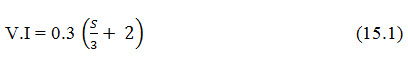
Where V.I = vertical interval between consecutive bunds [m], and s = land slope [in per cent].
The above formula does not take into account soil and rainfall characteristics and its applicability cannot be genera1ized. When the above formula is used for soils with high infiltration rate and good conservation practices such as contour farming, growing of cover crops etc., then 25% extra spacing can be used. On the other hand, in soils of low infiltration capacity arid unfavoub1e conservation measures, the spacing should be reduced by 15%. Similar adjustments are required for rainfall variation. For high rainfall areas, the interval should be reduced and vice-versa. In fact, a general relationship of the following form may be used and the constants should be evaluated for the specific site.
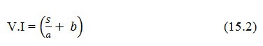
Where V.I = vertical interval between consecutive bunds [m], and s = land slope [in per cent]. The constants a and b should be evaluated for the specific soil and rainfall characteristics.
Cox’s Formula
M.P. Cox, a water management specialist of United States Agency for International Development (USAID) gave the following formula for spacing of contour bunds.
![]()
Where V.I = vertical interval between consecutive bunds [m], and s = land slope [in per cent].
y = infiltration and crop cover factor.
The values of x and y are given in Tables 15.1 and 15.2 respectively.
Table 15.1. Values of the Rainfall Factor (x) (Source: Mal, 1995)
|
Rainfall condition |
Value of x |
Annual Rainfall, cm |
|
Scanty |
0.8 |
64 |
|
Moderate |
0.6 |
64-90 |
|
Heavy |
0.4 |
over 90 |
Table 15.2. Values of the Infiltration and Crop Cover Factor
(Source: Mal, 1995)
|
Intake rate |
Crop cover during critical period |
Value of y |
|
Below average |
Low average |
1.0 |
|
average or above |
Good average |
2.0 |
|
One of the above two factors is |
||
|
favourable and the other is unfavourable |
1.5 |
For the purpose of moisture conservation mainly, the spacing of the bunds can be selected as given in Table 15.3. The recommendation is based on the works carried out by Gadkary in the former Bombay State.
Table 15.3. Spacing of Contour Bunds, (Source: Mal, 1995)
|
land slope, % |
Vertical interval, m |
Approx. horizontal distance, m |
|
0 to 1 |
1.05 |
105 |
|
1 to 1.5 |
1.20 |
97 |
|
1.5 to 2 |
1.35 |
76 |
|
2 to 3 |
1.50 |
61 |
|
3 to 4 |
1.65 |
52 |
|
4 to 5 |
1.80 |
39 |
|
5 to 6 |
1.95 |
36 |
Alignment and Construction of Contour Bunds
For the purpose of alignment and construction of contour bunds, a map showing the plan of the area is necessary. The map should either be available or prepared using any standard method like plane table survey. All natural features like streams, gullies, field boundaries etc., should be shown in the map. The area is then divided into blocks of suitable size (say 50 ha) in which soil conservation programmes can be taken up at a time. Detailed map of each block with a larger scale should be prepared. On these maps, the locations of the contour bunds are marked.
For drawing the position of the contour bonds on the map, at first lever survey is conducted by taking a suitable grid distance so that contours can be drawn on the map at an interval of 30 cm. From the contour map, average slope of the land is calculated. Knowing the slope, infiltration and rainfall characteristics, the vertical and horizontal intervals are calculated for the bunds. Planning is started from the top of the watershed. Contour bunds are located on the map as per the calculated horizontal interval. The positions are then transferred to the field. Slight modification is made to eliminate the sharp curvatures and changing of existing field boundaries. Another method in which the contours are directly located in the field can be used for alignment of contour bunds. This is known as direct contour method.
While using direct contour method, the slope of the land is determined approximately by taking flying levels. The vertical and horizontal intervals are calculated as describe earlier. Locating of the bunds is started from the top of the watershed. The dumpy level is set up at a convenient position. Leveling staff is held at one corner of the proposed location of the first bund and the reading is taken. The staff is shifted to different positions from where the same level readings are obtained. These positions are marked with pegs. Thus the position of the first contour bund is obtained. This procedure is repeated to obtain the positions of all the remaining contour bunds.
15.3.3 Graded Bunding
In areas of the high rainfall (annual rainfall greater than 800 mm) and fine textured soil, the entire runoff cannot be easily and economically stored in the catchment through contour bunding. The excess runoff may not safely be disposed of through the surplussing arrangement. Under such situations, graded bunds can be used to dispose of the excess runoff safely. Graded bunds have generally wide and shallow channels and earthen bunds laid along a pre-determined longitudinal grade. For a comparatively flatter slope of land, simply an earthen bund is constructed along a grade and water flows behind the bund. Therefore, contour bunds are mostly used for conservation of moisture in low rainfall areas with permeable soils. On the other hand, graded bunds are used partly for conservation of moisture and partly for safe disposal of the excess water in high rainfall areas and/or in tight soils.
Design Considerations
The design of graded bund includes determination of vertical interval (V.I.), grade and cross-section. Also a decision should be taken whether only the bund or a bund in combination with channel will be constructed. Only a bund is preferable as the problem of channel maintenance is eliminated.
Vertical Interval
The same principle as used for determination of the vertical interval and horizontal spacing of contour bund may also be used for graded bund. In case the soil is very permeable with high infiltration capacity and good biological control measures are practiced, the spacing of bunds can be increased by 25%. On the other hand for a fine textured soil without proper biological controls, the spacing may be reduced by about 15% from the calculated value.
Grade
Either a uniform or a variable grade is used for graded bunds. For short bunds of 100 to 150 m length uniform grade is used and for longer bunds variable grade is recommended. For most of the soils, grade can be in the range of 0.2 to 0.4%. In case of long bunds of 400 m or so in a permeable soil, the grade can be 0% at the beginning and increases to maximum 0.5% at the tail end. For impervious soil the grade at the beginning should be about 0.2% and increases to 0.4% at the tail end. The concept is to provide sufficient velocity of water so that an economical cross-section of channel can be obtained and at the same time the velocity should be non-erosive. The grade should generally change in every 100 m length. Short bunds of 100 to 200 m with channels (terrace) reduce the maintenance problems.
Cross-Section
The cross-section of the bund should be sufficient for stability, highest flood level should be below the top of the bund and the seepage line should lie below the toe of the bund on the downstream side. Generally a top width of 50 cm is used although it may vary from 30 to 90 cm for various heights of the bund. The height can be from 50 to 80 cm. Table 15.4 provides the dimensions of a typical trapezoidal shaped graded bund. The stable side slope depends upon the type of soil. For clayey soil it may be as steep as 1 : 1, for loamy soil 1.5H : 1V and for sandy soil it is increased to 2H : 1V. The seepage line has a horizontal to vertical slope of 3:1, 5:1 and 6:1 for clayey, sandy loam and sandy soils respectively. The base width of the bund should, therefore, be designed using this criteria and the depth of flow.
Table 15.4. Typical Dimensions of Trapezoidal Shaped Grade Bunds (Source: Mal, 1995)
|
Height, cm |
Top width, cm |
Bottom width, m |
Cross-section, m2 |
|
55 |
50 |
2.25 |
0.75 |
|
80 |
50 |
2.50 |
1.00 |
|
80 |
50 |
2.60 |
1.25 |
|
80 |
50 |
3.50 |
1.50 |
In case a channel is constructed in combination with the bund, the channel should have sufficient capacity to carry the excess runoff with non-erosive velocity. The non-erosive velocity ranges from 50 to 75 cm/s for soils varying from sandy to clayey type. The velocity also depends on the channel grade. Manning’s formula should be used to calculate the velocity of flow and the channel capacity. Generally, a cross-section of 1 m2 with a depth of about 45 cm serves the purpose in most of the cases. The channel may be designed for parabolic shape as it finally assumes that shape although originally it is constructed as a trapezoidal channel.
Alignment and Construction of Graded Bunds
The alignment of the graded bund can be done in a manner similar to that of the contour bund. As in contour bunds, the alignment can first be made on a contour map and then transferred to the field. They can also be aligned directly in the field. Before deciding the alignment of graded bunds, the location of the outlet and the grassed waterway should be finalized.
The reduced level (R.L.) of the outlet point of the topmost bund is determined. The distance along the contour is measured in a step of about 25 m and the elevation of the alignment is increased to provide the necessary grade. In case a variable grade has to be provided, the same procedure will work except that the rise in level at different steps will be proportional the grade. The outlet elevation of the second bund is obtained by deducting the vertical interval from the R.L. of the outlet of the first bund. Other points of the second and subsequent bunds are obtained in the similar manner as in case of the first bund. The alignment of a graded bund is shown in Fig. 15.1. The bund length in this case is only 100 m and a uniform grade of 0.3% has been provided. The vertical interval has been assumed to be 0.6 m.
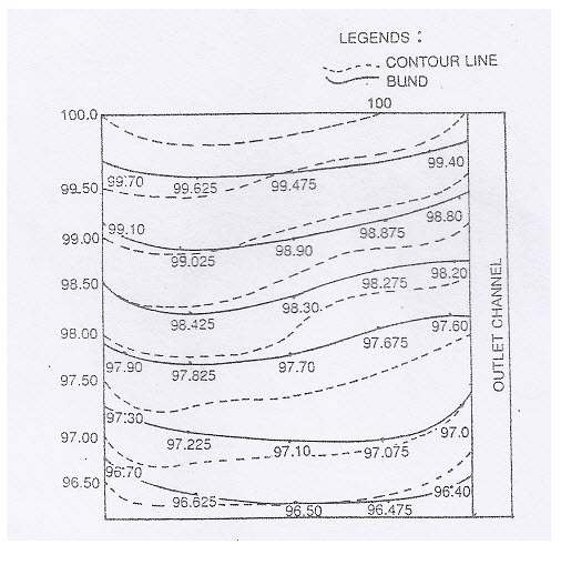
Fig. 15.1. Alignment of a Graded Bund. (Source: Mal, 1995)
The construction method of graded bund is same as that of contour bund. If manual labour is easily available, it can be used for making the bund precisely. Bullock drawn buck scraper can be used for scraping and filling the soil on the bund. Before that the soil should be loosened by ploughing. For large scale bunding, grade terracer pulled by wheel tractor, bulldozer, motor grade etc., are used. If a channel-cum-bund is constructed then the soil for bund should be obtained from the channel. Otherwise, the soil should be scraped from both sides of the bund for its formation.
15.3.4 Bench Terracing
Bench terraces are constructed to divide a steeply-sloped hilly land into a series of level or nearly level strips or benches running across the slope. The benches are separated by almost vertical risers retained by rocks or thick growth of vegetation. In India, bench terracing -although not very scientifically designed, has been very widely used for centuries. In the hilly regions of the north eastern states, Himachal Pradesh, Kerala, Tamil Nadu, Bihar, etc. farmers have been using bench terraces for growing crops.
Bench terraces are constructed on steep slopes greater than 6 to 7%, although recent recommendations favour their construction on slopes greater than 15%. Therefore, the cost of construction is very high and the construction is justified only when land available for cultivation is very scarce. The depth of soil should be adequate so that even after cut sufficient depth is available for crop growth.
Components of Bench Terrace
The bench terrace essentially consists of the four components namely, (i) riser, (ii outlet channel, (iii) platform and (iv) shoulder bund. Fig. 15.2 shows the components of a bench terrace. The riser is a vertical wall at the upstream end of the strip of land converted to bench terrace. The outlet channel can be located either at the upstream or at the downstream end depending upon the rainfall and soil conditions. Platform is the level or nearly level strip obtained by terracing and crop is grown in this zone. Shoulder bund helps to retain the rainfall in the terraced area.
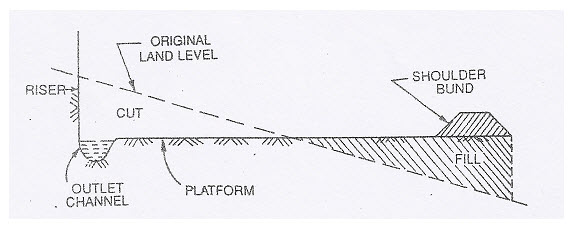
Fig. 15.2. Components of a Bench Terrace. (Source: Mal, 1995)
Types of Bench Terraces
Depending upon slopes, bench terraces are classified as (i) level bench terrace, (ii) outward sloping bench terrace and (iii) inward sloping bench terrace. Fig. 15.3 shows these types. There are other types such as California type terrace, Tati terrace, conservation bench terrace etc.
Level Bench Terrace: They are also known as table top or paddy terraces. They are generally used in paddy cultivation as paddy requires some ponded water. On a land of very mi1d slope such as 1% also level bench terrace is constructed to facilitate paddy cultivation. The level type is suitable in area with medium rainfall and permeable soils.
Outward Sloping Bench Terrace: In areas of low rainfall or shallow soil depth this type is suitable. The existing steep slope can be reduced to a mild slope to reduce soil erosion, conserve soil moisture and grow crops other than transplanted paddy. In case leveling is done in phases, this may be considered to be a step towards achieving a level or inward sloping terrace. The surplus runoff water should be safely disposed of through the provision of a graded channel.
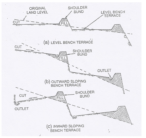
Fig. 15.3. Different Types of Bench Terraces. (Source: Mal, 1995)
Inward Sloping Bench Terrace: In high rainfall areas with steep slopes these types of terraces may be used. They have a drain on the inner side which is provided with a suitable grade along the length to convey the excess water to one side. Vegetated waterway is used to dispose of the water from such drains.
California Type Terrace: This is also known as Puerto Rican type terrace. At first, a vegetative or a mechanical barrier is established along the contour. Then the soil is ploughed and pushed downward gradually during tillage operations every year. Thus the terrace is developed slowly over a number of years.
Tati Terrace: The Tati terrace was first adopted in Tati village near Chandwa in Palamau district of Bihar by the Soil Conservation Department of the Damodar Valley Corporation (DVC). On lands having slope up to 3% and where contour bunds are not possible due to existing field boundaries, rectangular retention terraces known as Tati terraces are found to be more useful. Bunds are constructed on all or at least three sides following the revenue boundary so that water is stored and some leveling is done. Outlet is provided at one end and a vertical interval of about 60 cm is maintained.
Design Principle for Bench Terrace
Terrace design is influenced by the conditions of soil depth, slope, rainfall, farming practices etc. The design includes (i) terrace spacing, (ii) terrace grade and length, and (iii) terrace cross-section.
Terrace Spacing: The spacing is expressed in terms of the vertical interval (V.I.) and for this the following formula is generally used.
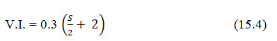
Here S = slope (%). But this formula cannot give a precise relationship for all conditions as the spacing depend upon slope, soil depth and surface condition and agricultural practices.
The depth of cut is influenced by the V.I. and depth of soil limits the maximum depth of cut. At the same time the width of terrace should permit economic agricultural operation.
Conservation Bench Terrace
In the conservation bench terrace (CBT), the terrace width is divided into two parts namely, the runoff part and the bench part. The upper part is the runoff part which is left undisturbed and contributes runoff water. The lower part is the bench part which receives the runoff water. The bench part is leveled by cut and fills method and generally a maximum depth of cut of 25 cm is used. A part of the excavated soil is used construct the two edge bunds and the laterals. The top soil is spread in the runoff part to smoothen the land surface to a uniform slope. At the junction of the runoff and bench part, a transition with a slope of 1.5H: 1V is provided. Grass turfing is provided to prevent scouring of this part.
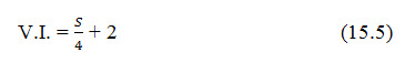
Depending upon the land slope, the CBT is divided into different width ratios. For a slope range of 0.25 to 1%, the ratio of widths of runoff part and bench part is 3:1. For slope range of 1 to 2%, it is changed to 2.5: 1. For a slope range of 2 to 4% the ratio may be 2: 1. The vertical interval (V.I.) of CBT is calculated in terms of slope [S, %] by using the formula.
The conservation bench terrace was developed and applied successfully as long back as in 1959 in semi-arid areas of USA by Zingg and Hanser. In different periods they have been applied in the arid tracts of Texas, Kansas, Eastern Colorado, Montana and North Dakota for various slopes ranging from 1 to 5%. The width ratio of runoff part to bench part is varied in the range of 1: 1 to 3 : 1 and the crop yield improved in the range of 18 to 36%. In India, CBTs have been successfully used in Bellary, Karnataka; Kota, Rajasthan; Hazaribagh, Jharkhand; Doon Valley, Uttarakhand and Midnapore, West Bengal. Red laterite soil of Midnapore with a slope of 1.5% and bunding at a spacing of 40 m, produced a maximum of 72% runoff in bare soil. Inter-cropping with maize and kalai (2: 5) reduced the runoff to 27%. In CBT system this runoff could be impounded in the bench part for growing paddy.
15.3.5 Grassed Waterways
Vegetated or grassed waterways are used for safe disposal of runoff from field,
traced areas, diversion channels, spillways or other structures. They either naturally exist or are constructed to particular shapes and dimensions. In case of construction, the vegetation in the waterway should be first established before any water is allowed to flow through it.
Functions: The grassed waterway may serve any of the following functions:
As outlets for diversions and terraces,
As outlets for farm ponds,
As outlets for emergency spillways,
To dispose of water collected by road ditches or discharge through culverts, and
To carry runoff from natural drains and prevent formation of gullies.
Location of Waterways and its Development
The waterways can be developed at a minimum cost by locating them in the
existing depressions as minimum earthwork will be required. Moreover, runoff water can flow from all sides without much modification of the topography. Also a minimum a disturbance of the existing field boundaries should be caused while deciding the location.
The grassed waterway is developed by first constructing it to a proper shape and
dimensions. Fertility is built up for growth of vegetation. Then the grass is planted either by transplanting sods or by seeding at suitable moisture content. During establishment of vegetation proper care is required to protect the waterway. Animals should be kept away during this period. Either the waterway should be constructed in advance of the channel that will discharge into it or the flow should be diverted during the period of stabilization. 1f any soil is washed away during the rains, it should be filled up and reseeded. After complete establishment of vegetation, only controlled grazing should be allowed. It should not be used as a Cart track.
Design Principles for Grassed Waterway
The grassed waterway is generally designed for expected runoff from a rainfall of 10 years recurrence interval. The design includes the shape, grade, design velocity and the cross-section of the waterway.
Shape: Generally parabo1ic triangular and trapezoidal shapes are used for waterways. Natural waterways have a shape very close to parabolic shape. Trapezoidal channels after a long use gradually approximate to the shape of a parabola. When a V-ditcher is used for construction, triangular shaped waterways are constructed. V-ditcher in combination with a buck scraper can construct a trapezoidal shaped waterway.
Channel Grade and Velocity: The topography of the land largely influences the channel grade. If the land slope is very high, channels should not run down the general slope to produce erosive velocity. The maximum grade should not exceed 10% and preferably it should be within 5%. The grade should be checked with maximum non-erosive velocity for various conditions by using Manning’s formula. The following values of non-erosive velocity should be used.
Table 15.5. Permissible Flow Velocities for Different Cover Conditions (Source: Mal, 1995)
|
Cover condition |
Permissible velocity |
|
1. sparse cover |
0.9 m/s |
|
2. Vegetation to be established by seeding |
0.9 to 1.2 m/s |
|
3. Dense, vigorous sod established quickly |
1.2 to 1.5 m/s |
|
4. Well established sod of excellent quality |
1.5 to 1.8 m/s |
|
5. Well established quality and conditions under which flow cannot be handled at lower velocity |
1.8 to 2.5 m/s |
Cross-Section: As explain earlier, the shape can be parabolic, triangular or trapezoidal for different shapes. The channel cross sections are designed as most economical sections.
Keywords: Water induced soil erosion, Contour cultivation, Contour bunding, Graded bunding, Bench terracing, Grassed waterways.
Reference
Mal, B. C. (1995). Soil and Water Conservation Engineering, Kalyani Publishers, pp. 316-378.
Suggested Reading
Murthy, V. V. N. and Jha, M. K. (2011). Land and Water Management Engineering, Kalyani Publishers.