Site pages
Current course
Participants
General
Topic 1
Topic 2
Topic 3
Topic 4
Topic 5
Topic 6
Topic 7
Topic 8
Topic 9
Topic 10
Topic 11
Topic 12
Topic 13
Topic 14
Topic 15
Lesson 15. Forces acting upon tillage tool/ implement and symbols used in tillage force analysis
Forces acting on a tillage implement or tool:-
- The engineers are concerned with the forces acting on a tillage implement because of:
i) Total power requirements
ii) Proper hitching or application of pulling force.
iii) Designing for adequate strength and rigidity
iv) To determine best shape and adjustment of tools
- A tillage implement (or tool) moving at a constant velocity is subjected to three main forces or force system which must be in equilibrium. These are:
i) Force of gravity upon the implement
ii) The soil forces acting upon the implement
iii) The forces acting upon the implement and the prime mover
If torque from rotary power transmission is not involved, the resultant of these forces is the pull of the power unit upon implement.
- Clyde sub-divides the total soil reaction into two:
Useful forces: Are those forces which the tool must overcome in cutting, breaking and moving of soil.
Parasitic forces: Are those forces (including friction and rolling resistance) that act on stabilizing surfaces such as land side and sole of plow or upon supporting runners or wheels.
- Under given set of operating conditions with a specific implement the operator has some control over useful soil-resistance forces. However, both designer and operator have some control over parasitic forces.
- If tool is not symmetrical about the vertical, longitudinal plane through its center line, useful soil forces usually introduce rotational effect.
If P = Pull exerted by power unit has components in all the major planes and associated with it is a couple.
R = Resultant of all useful forces acting upon tool or implement.
Let us resolve the forces in three components L, S, V.
L = Horizontal component also called draft.
V = Vertical componentIt removes load from the front wheel of tractor and effects on tractive ability of tractor, stability and steerability. It helps in penetration and maintains working depth.
S = Side draft or force.Maintains directional stability on tractor and implement and affects on draft of implement because of frictional forces.
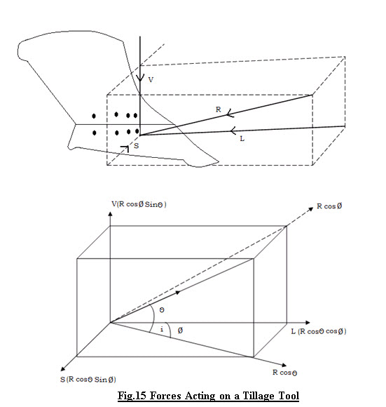
- From Fig. 15
L = R cosθ cosф
V = R sinθ cosф
S = R cosθ sinф
Where; θ = Angle of inclination of ‘R’ in vertical plane with horizontal.
ф = Angle of inclination of ‘R’ in transverse plane with horizontal.
- For mounted implements supported and pulled by tractor, this force P between implement & tractor in vertical plane is force containing L & V component
P = √L2 +V2
= √R2 cos 2 θ cos 2 ф + R2 sin2 θ cos 2 ф
= √R2 cos 2 ф ( cos 2 θ + sin 2 θ )
= R cos θ
- As tools are not symmetrical about vertical and longitudinal plane. There are different ways of expressing total soil reaction on tillage tool with rotational effect
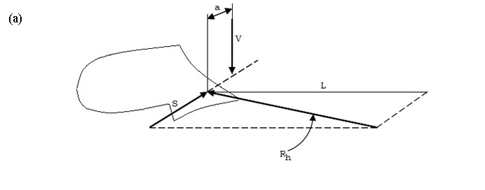
Fig. 16 (a) Two non-intersecting forces RL & V
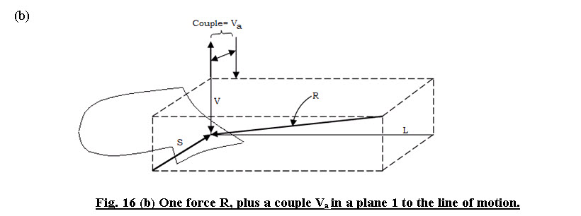
c) A wrench i.e. one force plus a couple in the plane perpendicular to the force.
(d) Three forces on mutually perpendicular axes and three couples in the planes of intersection of axes.
(e) Three forces in three major planes.
- Results of force measurements may be represented by any of these five methods and results expressed in one form can be transposed to another form by method of statics.
Typical Location of Rh and its relation to the Landside Force and Pull
Following discussion force R and its components L, S, V, Rh & Rv refer to resultant of useful soil forces Q indicates parasitic force & P, Pv , Ph and Px (draft) include effect of both useful and parasitic forces and force of gravity.
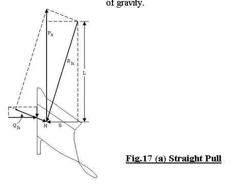
Horizontal force relations:
-
Horizontal component L equal and opposite to Rh
Rh - Resultant of L & S.
-
There is no side force on landside and draft = -L
-
When horizontal Pulling force is in the direction of travel i.e. Px (draft) Parasitic side force automatically introduced on landside to counteract S.
-
Qh = Resultant of side force and accompany friction force on landside.
-
H = Intersection of Rh & Qh.
It is the horizontal location of center of resistance of plow bottom.
If Pull is angled to left (fig. (b))
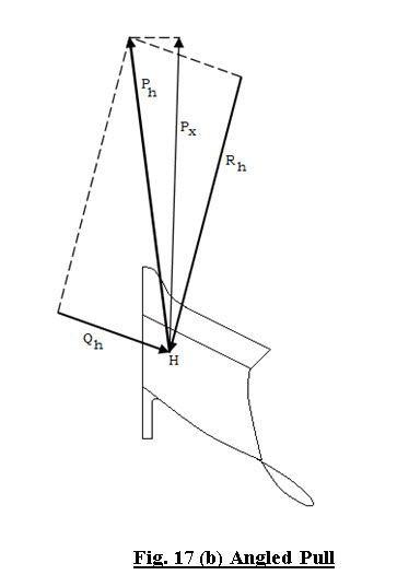
Ph = Component of P in horizontal plane.
It increases land side force and increase Px (draft) more.
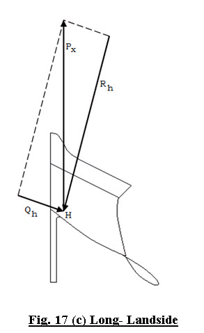
Fig. 17 (c), increasing the landside length Qh (Parasitic force) moves to rear.
Thus, H has to be relocated, farther back.
Now H is closer to landside as line of Rh does not change. Taking most of side force on rear furrow wheel has similar effect.
(b) Vertical force relation:
- Mould board plow has downward acting vertical component.
- Magnitude of V in relation to L varies widely and influenced by
- Soil type
- Soil condition
- Depth of cut
- Share edge shape
- Share sharpness.
- Penetrating ability is important characteristic.
- In case of mounted and semi-mounted implements V contributes directly to vertical load on tractor rear wheels and increases load transfer from front wheel to rear wheel.
- Shares with downward Pitch Point (extended forward beyond the line of share edge) have greater suction (downward V) than straight shares, particularly at shallow and moderate depth.
- Share having top beveled - less downward V
- Share having bottom beveled - more downward V
- Leading portion of bottom slightly higher than rear portion reduces V and increases soil compaction.
Last modified: Thursday, 20 March 2014, 11:12 AM