Site pages
Current course
Participants
General
Topic 1
Topic 2
Topic 3
Topic 4
Topic 5
Topic 6
Topic 7
Topic 8
Topic 9
Topic 10
Topic 11
Topic 12
Topic 13
Topic 14
Topic 15
Lesson 17. Hitching System, Forces for Handling Implements and Control of Implements
Hitching System:
-
A plow or implement may be well designed and built of high-grade material but unless properly hitched it cannot give the best performance.
-
Primary objective of proper hitching of pull-type implements having adjustable pull members is to establish location and/or magnitude of the resultant parasitic support forces (Q or Qv) and pull (P or Pv).
These are desirable from the stand point of the effects of the pulling force upon tractor and magnitude and distribution of parasitic forces acting upon the implement.
- Force relations for mounted or semi-mounted implements are determined primarily by the design of hitch linkage and implement and by the method of controlling implement depth, rather than by hitch adjustments.
Mould Board trailing Plow Hitches:
Perfect hitch for a trailing plow to have the center of pulled load directly behind the centre of power unit but this condition can rarely be obtained because of different widths of different size tractors and the different widths and sizes of plows or pulled units.
Hitch Systems and Hitching Tillage Implements:
Force relation is involved in hitching pull type of implements. Useful soil forces components L, S, V and implements gravitational force W are independent force variables and analyze simple drawbar hitch arrangement or integral hitch systems. Parasitic soil forces Q and pull P are dependent variables and can be influenced by hitch arrangement. Analysis of force relation considering horizontal components R, Q, P and W is horizontal hitching and components of these forces in vertical plane is vertical hitching. Primary objective of proper hitching for pull type implements having adjustable pull members is to establish the location and magnitude of the resultant parasitic support force (Qh or Qv ) and pull (Ph or Pv). Force relation for mounted or semi-mounted implements is determined by design of hitch linkage and implement and by method of controlling implement depth, rather than by hitch adjustments.
Horizontal hitching of pull type Implement:
M.B. plow, disk plow, offset disk harrow are not symmetrical about their longitudinal center lines. Most of other implements are symmetrical about their longitudinal center lines, side components of soil forces are balanced, horizontal centre of resistance is at centre of tilled width and horizontal line of pull is in direction of travel. Plows and offset disk harrows can withstand substantial amounts of side draft (lateral component of pull) so proper hitching is must to minimize adverse effects on tractor and implement. M.B. plows absorb side forces through landsides, disc plows throw furrow wheels, offset disk harrows by automatically changing disk angles to create a difference between soil-force side components for front and rear gangs. Pull type disk plows have free-link pull members. M.B. plow and disk harrows have laterally rigid pull members. It is not always possible to have a horizontal centre of resistance of an implement directly behind the centre of pull of tractor particularly for narrow implements and wide-tread tractors. This implement can withstand side force, alternatives are:
- Central angled pull passing through centre of pull of tractor
- offset straight pull
-offset angled pull
If implement cannot withstand side force only alternative is:
- an offset straight pull.
Centre of pull of tractor is midway between rear wheels and slightly ahead of axle as differential divides torque to wheels equally. Central angled pull does not affect tractor steering but offset pull does. Angled pull introduces a side force on tractor rear wheels and is undesirable with same implement even though implement can resist side force. So a compromise in hitching is best with a part of adverse effect absorbed by tractor and part by implement.
Horizontal Hitching of pull type implement:-
As determined earlier, location of horizontal control of resistance, H for a M.B. plow is determined by the point of intersection of parasitic force Qh acting upon landside and Rh (Fig. 17.1). Lateral location of H varies depending upon soil conditions, length of landside, amount of side force taken by rear furrow wheel etc.
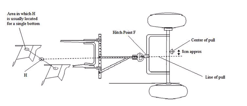
Fig. 17.1 Horizontal hitching for a mold board plow pulled by wider tractor
For hitching, its location can be assumed to be one-fourth of the width of cut over from landside and little behind the rear edge of the share. Line of pull is determined by location of H and location of drawbar hitch point F as pull members are laterally rigid. Ideal hitch is obtained when tractor tread can be adjusted so the control of pull is directly ahead of horizontal centre of resistance. Normal tread of 52 inches can be adjusted to 48 inches. When a central straight pull cannot be obtained, it is better to divide the effect of offset so that line of pull passes a little right of centre of pull but not enough to cause steering troubles.
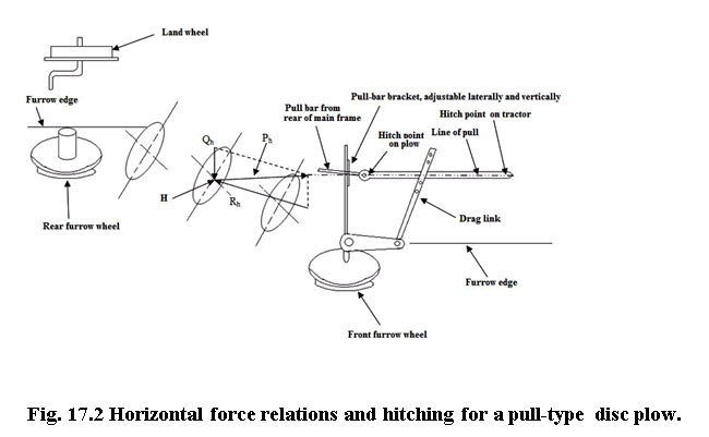
Horizontal hitching of a pull type disc plow:-
All the side thrust must be taken through the wheels and pull members, which is a free link in regard to horizontal forces. Horizontal line of pull for a disk plow is determined by location of hitch points D & F (Fig. 17.2). The position of horizontal centre of resistance H and location of resultant side force Qh are established by point of intersection of Ph and Rh. Side forces are divided equally between front and rear furrow wheels. Line of Qh must pass midway between them. If hitch point D is moved to left of plow frame, H and Qh move toward the rear of plow, and rear furrow wheel will have more side thrust. Moving D to left or F to left, pull puts more side force on front wheel.
Vertical Hitching of Pull Type Implement
Types of Vertical Hitching Systems:
Pull-type tillage implements fall into one of the following three categories:-
Implements with hinged pull members that have support wheels or support runners to gage the depth. The pull members act as a free link in the vertical plane, e.g., M.B plow, disc plow and drag type spring tooth harrow, etc.
Implements with hinged pull members that do not have gage wheels or runners. The only support is through soil-working units and parasitic forces cannot be separated from useful soil forces, e.g., disc harrows without wheels, spike tooth harrows and tandem-gang rotary hoes.
Single-axle implements with rigid pull members, e.g., field cultivators, chisels, sub-soiler.
Implements having Hinged Pull members and Support Wheels or Runners:-
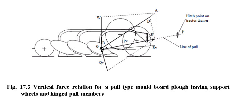
Vertical force relation for a pull-type M.B. plow has been shown in Figs 17.3 and 17.4. For uniform motion W, Rv, Pv, and Qv must be in equilibrium. Magnitude and location of implement gravitational force W and useful soil force Rv combined graphically into resultant AB. Thus the Line of pull must pass through the hitch point F on the tractor and hitch hinge axis selected at E, since pull member acts as a free link in the vertical plane. The Line of pull and resultant AB intersect at G. Support force Qv is drawn with some backward slant to include the rolling resistance of wheels furnishing the vertical support. More slants would be needed, if support were on sliding surfaces, to include the friction force.
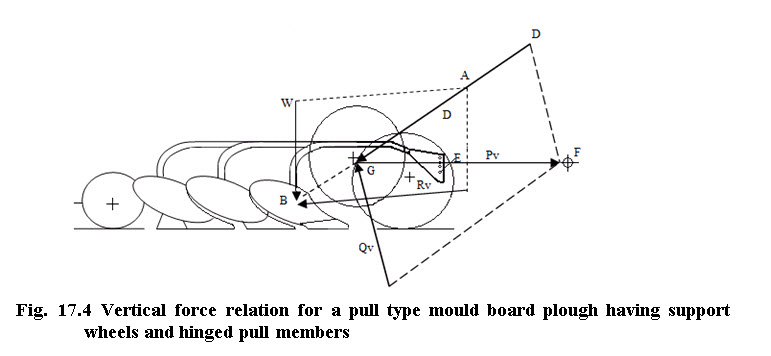
Pv is in equilibrium with AB, and QV, magnitude of Qv and Pv can be determined by moving AB and DG and completing the parallelogram. Fig 17.3 shows desirable hitch adjustment for a mould board plow with Qv located well behind the front wheels. So, there is enough load on rear wheel for stable operation. Fig. 17.4 indicates that as hitch point E is too high on plow then Qv is under the front wheels with no load being carried on the rear wheel. Therefore the rear of plow will be very unstable, especially when momentary variations in the direction and magnitude of Rv are considered.
Hitching at too low point on implement has opposite effect. Resultant force Qv is moved toward rear and reducing load on front wheels. Thus, by increasing or decreasing the slope of Pv without changing the location of G, decreases or increases Qv but it does not change its location.
Very high slope for Pv can cause difficulty in maintaining desired depth, particularly with light implements that have little or no suction such as spring tooth harrow. Therefore, for mould board plow, adjustment of hitch height on plow frame should be such that Pv passes through a point slightly below the ground surface and directly above the average location of all share points. Similarly, for disk plow, line of pull is at ground surface midway between the center of front and rear discs. If rear furrow wheel of a disc plow has a lead towards the plowed ground and tends to move out of the furrow then the hitch point on plow frame should be lowered which will put more of Qv on rear wheel.
b) Implements with hinged pull members but without gage wheels or runners.
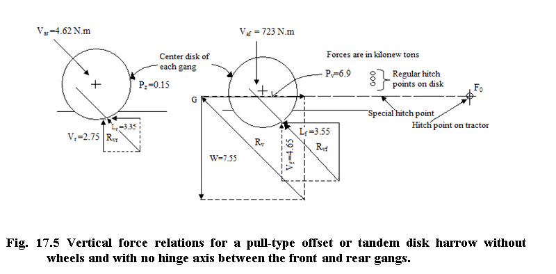
Vertical force relation for an offset or tandem disk harrow without wheels is shown in Fig. 17.5. The support from soil is through the disc blades and the position of point G is obtained by the intersection of W and line of pull, Pv. The soil forces Rvf and Rvr are adjusted by means of depth changes. Therefore resultant Rv passes through point G and is in equilibrium with W & Pv. Raising the hitch on implement frame, raises G and moves Rv closer to front gang, thus Rvf increases and Rvr decreases. Thus, depth of penetration will increase for front gang and decrease for rear gang. Rvf is larger than Rvr as front gang is operating in firm soil and rear gang in loose soil.
Single – axle implement with rigid pull members:-
Fig. 17.6 shows the vertical force relation for a single-axle, pull-type implement receiving vertical support only though its wheels. In this condition, the location of Qv is fixed. The Qv passes slightly behind the axle center line to supply torque which overcomes wheel bearing friction and causes rotation of wheels. Also point G is fixed by intersection of AB and Qv. Line of pull is through G and vertical hitch point F at tractor drawbar.
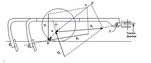
Fig. 17.6 Vertical force relations for a single-axle, pull type implement receiving vertical support only through its wheels.
Possible hitch adjustment is changing the height of drawbar at F, which would change the slope of Pv. In fig., Rv has downward slope which moves the wheels rearward with respect to soil-engaging tools and will increase the slope of Pv and reduce the magnitude of Qv.
HITCHES OF MOUNTED IMPLEMENTS
Design considerations and types of Linkages:
Generally two types of hitch linkages are used on tractor rear mounted three point converging-link types. The rear mounted three point parallel link type hitches for front mounted cultivators are not common in India. Single axis hitches are replaced by three point hitches. Any of these types can be operated with hitch members acting as free link in vertical plane or restrained links.
Factors considered in designing or evaluating a system for mounting tillage implements on rear of tractors:-
Ease of attachment and adjustment, versatility and safety.
Standardization to permit inter- changeability.
Uniformity of tillage depth as the tractor passes over ground surface irregularities.
Ability to obtain penetration of implement under adverse conditions, particularly with implements such as disk harrows and disk plows.
Rapidity with which tools such as plows as listers enter the ground.
Trailing characteristics of implement around contours and on side hills.
Effect of implement upon tractive ability of tractor (vertical load transfer from front wheels to rear wheels).
Effect of raised implement upon the transport stability of the tractor.
Three point hitches:
Hydraulic control systems were introduced on tractors in late 1930s. No. of hitching arrangements for rear mounted implements were developed. Most common among these is three-point hitch system. The two lower links cover toward the front and are free to swing laterally within limits. The lower links can also be locked. So, they are laterally rigid, which is desirable in some non-tillage applications. ASAE-SAE standards for 3-point hitches specify all dimensions related to 3 connecting points between implements and tractor and minimum limits for lift height, Lateral leveling adjustments, side sway and minimum lift force to be available at hitch pins. Link lengths and amount of horizontal and vertical convergence are not specified. Maximum drawbar power available for different ranges of categories are:-
Category I - 15 to 35 kW (20 to 45 hp)
Category II - 30 to 75 kV (40 to 100 hp)
Category III - 60 to 168 kW (80 to 225 hp)
Category IV - 135 to 300 kW (180 to 400 hp)
Quick attaching couplers for three point hitches have been developed to facilitate the attachment of implements that are too heavy to be nudged into position by one man. These have been standardized to fit on the standard three-point linkage system. Quick attaching couplers allow the operation to couple or uncouple an implement without leaving the tractor seat thus contributing to both convenience and safety.
Free-link operations of 3-point hitches:
Depth control from mounted mould board plow can be obtained through vertical support from rear furrow wheel and heel of rear land side. When free-link operation is desired, depth is controlled by gage wheels running on unplowed ground. Fig. 17.7 showed vertical force relations for
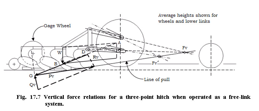
free- link operation with M.B. plow having a gage wheel. In free-link operation convergence of links in a vertical plane provides a vertical hitch point or instantaneous centre of rotation as shown at Fv. Location of Fv can readily be changed by modifying arrangement of links and it shifts automatically as implement is raised or lowered. Location of Fv is shown by dotted lines. It is lower than Fv and farther to rear when tool is entering the ground. This shift promotes rapid entry of tools that have appreciable bottom support surfaces (such as a M.B. plow). Force analysis is same as that of single-axle, pull type implement. Line of pull, Pv must pass through virtual hitch point, Fv. All vertical support is assumed to be on the gage wheel and establish the line of action of Qv. The slope represents the coefficient of rolling resistance. W & Pv are combined into resultant AB. Location of G is established by intersection of AB and Qv. Pv then passes through G & Fv. Raising Fv by modifying the linkage would reduce Qv and increase the load on tractor rear wheels. But Qv must not be reduced to the point where the implement becomes unstable due to momentary variations in Pv. Also increasing the plow length by adding more bottoms would move R, W, Qv and G farther to rear, Pv in that case would have less slope but higher above the ground at tractor wheels. Gaged free link operation gives more uniform depth than either automatic position control or automatic draft control when field surface is irregular and soil resistance varies particularly with large size mounted M.B. plows. Gage wheels are sometimes used with other systems in light soils where draft is relatively low. Wide field cultivators and chisels have gage wheels to minimize depth variations across the width of implements.
Restrained-Link Operations of Three-point Hitches:
In restrained link operations, implement gets its vertical support from the tractor. Hitch links are free only when tool is entering the ground. Since implement obtains no support from soil, Pv is in equilibrium with W & Rv. Lift links are in tension and implement exerts downward bending moments on the portions of lower links behind lift links. With restrained link operation the effect of implement upon the tractor is that when the implement is at its operating depth it is independent of hitch linkage arrangement. Line of pull Pv
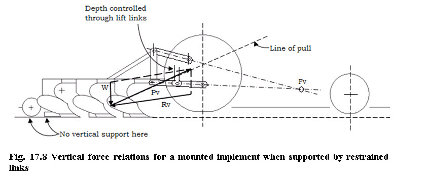
will pass through intersection of W and Rv (Fig. 17.8). If implement is operating with restrained links, it will increase the vertical load on tractor rear wheels and provide greater tractive ability. This is because the location of Pv is higher at rear wheel and this will increase the load transfer from front wheels to rear wheels. When the implement is suspended at a fixed height with respect to tractor, as with automatic position control, depth fluctuations caused by ground-surface irregularities are greater than with gaged free-link arrangement. Magnitude will increase in direct proportion to the amount of overhang of implement behind the tractor rear axle.
Automatic Draft Control:
This is a type of restrained link system in which depth of implement is automatically adjusted to maintain a preselected constant draft. If soil resistance is uniform, depth fluctuations caused by irregular ground are less with automatic draft control than with automatic position control. In field, depth will vary as a result of variations in soil resistance, regardless of whether the field is smooth or undulating. In smooth fields, automatic draft control maintains average draft within the available power or tractive ability of tractor. When an overload condition occurs, automatic draft control system attempts to lift the implement against gravity and its inertia and against any downward soil force components. The lifting action behind the tractor results in a counter balancing lifting action of front wheels. Thus, momentarily vertical load from both implement and front wheels transfers to drive wheels and minimizes wheel slippage. If excessive soil resistance persists over any appreciable distance, implement depth is reduced.
Draft Sensing:
Earlier upper link draft sensing was employed on all automatic draft control systems and it is still in use on small and medium size tractors. With mounted implements the upper link is always in compression when implement is in ground.
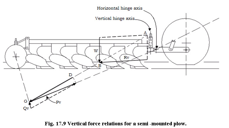
Vertical hitching relations for a Semi-mounted plow
A semi-mounted plow is usually attached to two lower links. All the vertical support force from soil will act upon rear furrow wheel. Qv is somewhat forward from rear wheel. W, the gravitational wt. of implement is larger than Rv as semi-mounted plows are 50% heavier per bottom than mounted plows. Line of pull Pv must pass through horizontal hinge axis provided at the three-point hitch (Fig. 17.9). Locating hinge axis higher on frame would raise Pv and thereby increase the vertical load transfer to rear wheels.
 Vertical effects upon the tractor:-
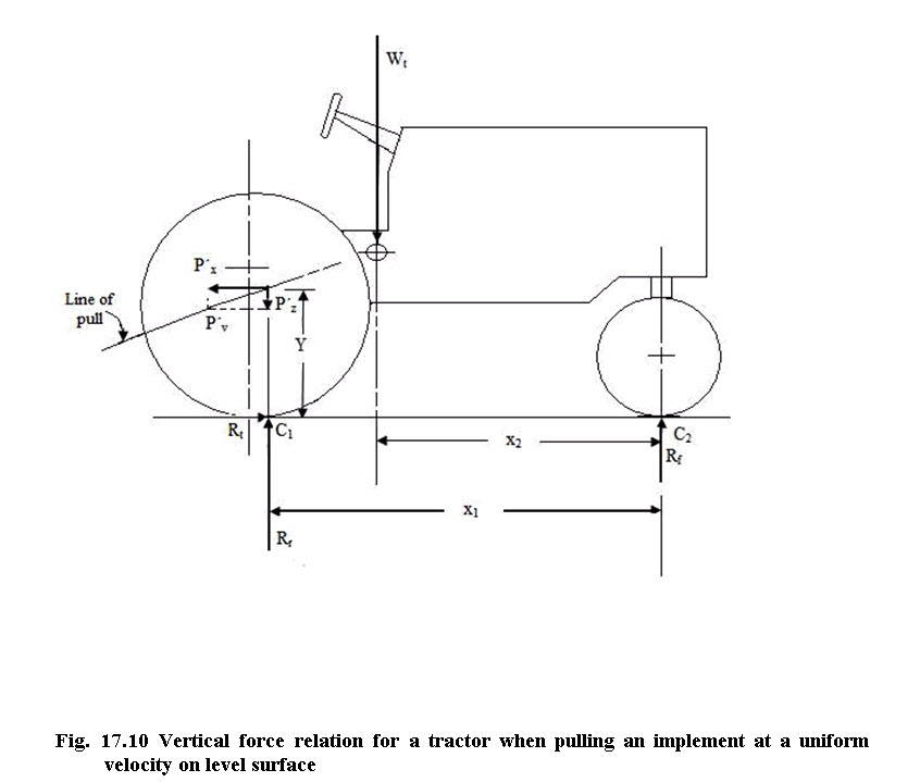
When magnitude and line of action of Pv are known, the effect of implement upon drive wheel loading of tractor can be determined. Rt & Rf are vertical supporting soil reactions on wheels. Rt is tractive effort. Rr is slightly in front of rear axle (25 to 50 mm approx.) because of rolling resistance of tractor, bulldozing etc. Pv is the pull of implement on tractor. It is equal and opposite to Pv. Pz and Px are vertical & horizontal components of Pv. Distance Y is height above the ground at which Pv intersects the vertical line of action of Pr. Wt is the force of gravity on the tractor acting through the centre of gravity (Fig. 17.10).
Taking moments about C2
Rrx1 – Wt x2- P’zx1- P’xy = 0
x2 y
Rr = Wt (---) + P’z + P’x (---)
x1 x1
- Taking moments about C1
Wt (x1 – x2) - P’xy - Rfx1 = 0
x1 – x2 y
Rf = Wt (----------) - P’x (-----)
x1 x1
These equations show the effect of implement pull is to add vertical force P’Z to rear wheels and to transfer vertical force equal to P’x y/x1 from front wheel to rear wheel, thus increasing the tractive ability.
Horizontal Effects of Hitching:
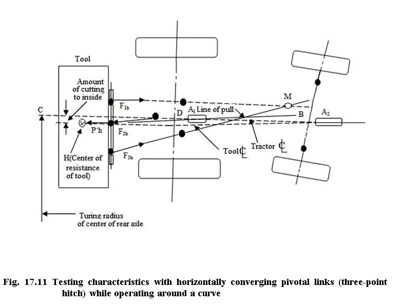
The important characteristic of a mounted implement is that a uniform width of cut is obtained when operating around contour without affecting tractor steering. If rear mounted implement is not permitted lateral movement with respect to tractor, implement will cut outside while operating on contour and steering response is also poor because side forces will be developed by implement. The lateral swinging hitch gives easy steering but implements cut soil to the inside on a corner. Fig. 17.11 shows a mounted implement on a three-point hitch. The lower links converge towards the front and are free to swing laterally. The tractor operating on a curve M is centre of rotation of two lower links but it is not virtual hitch point. The line of action of the force in the top link does not pass through M, the sum of the forces in the three links lies along line BH which passes between M and the tractor centerline. It is the horizontal center of resistance of the implement and BH is the line of pull. Ph is the pull of the implement upon the tractor and is in equilibrium with F1h, F2h, and F3h. The direction of Ph can be determined from the linkage geometry in the vertical and horizontal planes. A non directional implement (i.e., one that has little or no resistance to side forces) tends to move along the line of pull when the tractor is on a curve, the linkage adjusting itself so that BH is perpendicular to a radius drawn through H and the turning center for the tractor. The effect is the same as that of a trailed implement pulled from a point within the small area A1 on the tractor center line. The implement cuts the corner more than it would if M were the virtual hitch point. The total amount of corner cutting is the distance from H to arc CD, as indicated in Fig. 17.11. Some implements, such as a moldboard plow or a cultivator equipped with a guiding coulter or fin, are directional. Within reasonable limits they tend to go in the direction in which they are pointed, rather than in the direction of pull. In this case the implement is pulled toward the virtual hitch zone A2, representing the intersection of the implement center line and the tractor center line and the implement adjusts itself so A2H is perpendicular to the radius line through H. Since A2 is farther forward than A1, a directional implement cuts the corner even more than an implement that is free to move in the direction of pull. For ideal trailing of any implement around a curve (no corner cutting), the horizontal hitch point (real or virtual) should be on the tractor center line, equidistant from the center of resistance of the implement (H) and the center of pull of the tractor (D). On a side hill, however, where the rear of the tractor tends to slide downhill, the lateral position of the implement will be affected least when the hitch point is well forward on the tractor. A hitch point somewhat forward of the rear axle is also best in regard to ease of steering. Thus a compromise must be made to determine the best overall location for the horizontal hitch point for mounted implements.
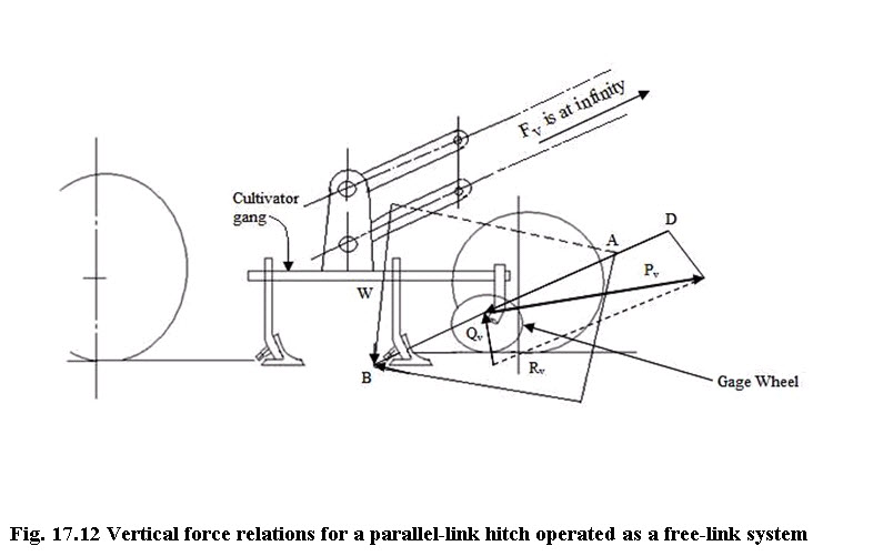
Parallel link Hitches:
Generally used on mounted row coop cultivators because raising or lowering the gang or tool bar changes the depth of all shovels by the same amount and does not change the pitch of shovels. Also the lateral rigidity of the hitch is important to permit cultivating close to plants. In case of restrained link operation, depth of cultivation is controlled through the listing mechanism. The free-link operation with gage wheels is common on wide tool bars and on multiple-gang cultivators. The virtual hitch point for free link operation (Fig. 17.12) is at the intersection of parallel links or at infinity. Pv is parallel with the links and magnitude of Qv can be changed by changing the slope of links. Moving the gage wheel forward or backward has no effect on magnitude of Qv.
Load transfer Systems for pull –type implements:-
Load transfer with pull-type implements as a means of increasing tractive ability of larger tractors is important. There must be some arrangement for applying moment to the implement pull member which tends to lift the rear end of pull member and front of implement. Pull member is strong enough to withstand these forces. Vertical load from implement and tractor front wheel is transferred to tractor drive wheel. This transfer tends to reduce the depth of same type of implements. Maximum acceptable amount of implement vertical-load reduction is influenced by soil conditions, implement mass and type, method of controlling or gaging depth, tractor front end stability and steering response. Load transfer system requires same modification or addition to implement pull member. Other systems pull from regular tractor drawbar and exert a constant lifting force by means of an adjustable, constant hydraulic pressure applied to rockshaft lift cylinder.
Last modified: Monday, 24 March 2014, 9:47 AM