Site pages
Current course
Participants
General
Topic 1
Topic 2
Topic 3
Topic 4
Topic 5
Topic 6
Topic 7
Topic 8
Topic 9
Topic 10
Topic 11
Topic 12
Topic 13
Topic 14
Topic 15
Lesson 19. Study of miscellaneous tillage tools, rotary tillage tools, rotavators, stirring plough, auger plough, rotary hoes, Oscillating tools etc.
VIBRAORY AND OSCILLATORY ILLAGE
This type of cutting tool either vibrates or oscillates. Their primary object is to reduce draft and to improve overall energy utilization efficiency in soil break and provide semi control over the degree of pulverization. These implements reduce draft as much as 50-75% in comparison with non-oscillating tool. Draft reduction is desirable especially with high draft implements like sub-soilers. Operating parameters for a vibratory tillage system include:-
Travel speed
Oscillation frequency
Amplitude
Direction and pattern of oscillating motion
Tool shape
Tool lift angle
Soil physical characteristics.
The effects of frequency and amplitude tend to diminish rapidly as their values increased beyond optimum values. Several studies resulted that effect of vibration were most pronounced at frequencies that resulted in a forward travel per cycle which was about to or slightly less than the spacing of natural shear planes caused by a non-oscillating tool. This relation makes the optimum frequency a function of soil physical characteristics. Although oscillation of tillage tool has reduced draft but there is little reduction in total energy requirement and sometimes there is substantial increase. That means oscillation conditions that causes large reduction in draft are not best for total energy requirement.
Principle of Vibratory Tillage:-
Vibration causes physical changes to take place in the soil that tend to reduce shear strength. And for maximum draft reduction tillage tool should be oscillated in such a manner that there is definite separation of cutting and soil-lifting operation to minimize soil-metal friction shown in Fig. 19.1 (a), (b), (c)
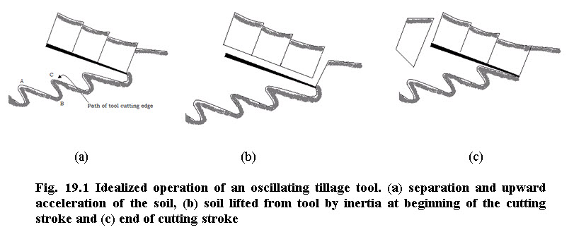
In this Fig 19.1 the tool is pivoted at one point above and it is somewhat ahead of cutting edge. Due to this a forward stroke cutting edge moves downward along point AB. Shearing action takes place on return stroke (Fig a ). Since there is little or no forward motion of tool during this operation so energy for shearing, lifting and accelerating the soil upward does not contribute to draft. (Fig b and c) upward motion of soil plus the fact that soil is loose this minimize the friction against upper surface of tool during forward stroke. Tool makes a new cut at a flat angle with little lifting of block being cut (Fig. c). If relation between oscillation angle, tool lift angle and forward travel/cycle is correct there is adequate clearance beneath the tool body. So, in this idealized situation the draft requirement is to overcome cutting resistance and minimal frictional forces of newly cut soil sliding on upper surface of tool.
Multi-powered Rotating Tillage Tools:-
There are various configurations available viz. Vertical axis - unit, Longitudinal axis – unit and Transverse – axis unit.
Vertical axis
These machines have series of two tine vertical rotors across the width of machine.
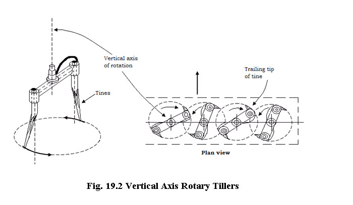
The path of adjacent rotor overlaps as shown in Fig. 19.2. Gear on upper ends of rotor shaft transmits power from one rotor to other and provide counter rotation of adjacent rotor. Good for pulverization and secondary tillage. Do not work well in loose surface trash.
Transverse axis:
Rotary spading machine is an example of transverse axis type rotating tools. It has transverse, powered rotor with spades attached to arms on it. Mechanical complexity and lack of durability are problems, trash coverage is poor. They are comparable in regard to soil pulverization and energy requirements. Work well in heavy soils.
Rotating Auger Plow:
It is a kind of mould board plow on which rear portion of mould board are replaced with powered rotor. Rotors have teeth (Blades) to assist in soil pulverization. Draft is less than the conventional M.B. but total power requirement is high. Soil pulverization is unsatisfactory in dry, compact soil. Trash coverage poor and driven rotor make this implement more complex and expensive than conventional plow.
Conventional Rotary Tillers:
Blades are attached on flanges along a horizontal shaft that is perpendicular to the direction of motion. Swiss made introduced in 1930 in U.S. Early models were small garden unit. Now heavy-duty tractor mounted or pull type unit width ranging from 1 m to 4 m are used. Tractors using these units for primary tillage should have 0.3 kW PTO power per cm of tilling width (1 PTO HP/inch). Power requirement is high for primary tillage. Degree of pulverization (excessive) is very high. Good for strip tilling, preparing precision seed beds for planting, cutting vegetative matter and mixing it throughout the tilled layer of soil. But coverage is not as complete as with mould board plow. Widely used in rice fields in south east. Asia, China, Japan, Korea. Rice soils are often puddled by means of rotary tillers.
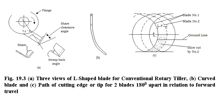
Many types and shapes of blades are developed (Fig. 19.3 a)but hoe types are common. L-shaped blades work well in trashy conditions, they kill weeds more effectively and do not pulverize the soil much. Power requirement is high. Curved blades for special situations such as operating on sides of plant beds ‘C’ type less power requirement than ‘L’.
Rotor Speed – 250 – 300 RPM dia of Rotor = 46 cm:
Rotar rotates in the same direction as the tractor wheels.
Each blade cut a segment of soil as it moves forward and towards the rear.
Most rotary tillers make 2 or 3 cuts per revolution along any one longitudinal line.
Bite length ‘F’ is defined as amount of forward travel per cut. It can be increased by reducing rotor speed or by increasing forward speed.
Slice thickness varies during the cut and also the force.
High peak torques developed during each cut require staggering of blade in different courses, with equal angular displacements between them. So no two blades strike the soil at same time.
Blades experience an upward component of force ‘V’ and a forward component ‘L’. Relative magnitudes of these forces are influenced by depth, rotor dia, bite length, soil type and condition, type of blade, share (Blade, c clearance angle.
Upward component reduces the amount of implement gravitational force that must be supported by gage wheels or tractor. Under some conditions it causes rotor to walk out of ground.
Forward component results in negative draft and –ve specific energy requirement for traction, both increasing inmagnitude and bite length.
Forward thrust from –ve draft is troublesome to tractor stability and design.
Researches shows that –ve power requirement represented by forward thrust was less than 7% of rotor power when bite length was 5 cm and 20% of rotor power when bite length was 15 cm.
Last modified: Monday, 24 March 2014, 10:18 AM