Site pages
Current course
Participants
General
20 February - 26 February
27 February - 5 March
6 March - 12 March
13 March - 19 March
20 March - 26 March
27 March - 2 April
3 April - 9 April
10 April - 16 April
17 April - 23 April
24 April - 30 April
Lesson 2. THE BENCH WORK TOOLS AND ITS USES
THE BENCH WORK TOOLS AND ITS USES
2.1 Introduction
Bench work has its own essential position in all engineering works. In the mechanized workshops, where most of the work is carried out on an automatic machine, while bench work has its own importance. The jobs can be finished to a fairly good degree of accuracy through machining operation; they often require the hand operations to be done on them to finish to the desired accuracy. A fitter’s work is unavoidable when different parts are to be assembled in position after they have been finished. Alignment of machine parts, bearings, engine slide valves and similar other works call for a fitter’s work. Reconditioning and refitting of machines and machine parts cannot be done without a skilled fitter. All the above types of works require the use of a large number of hand tools and a fitter must have good working knowledge of all these tools and instruments.
2.2 Filter’s vices
Vices are the most suitable and widely used tools for gripping different jobs in position during various operations carried out in a fitting shop.
There are a fairly good number of different types of vices such as parallel jaw vice, machine vice, hand vice and pipe vice.
From these, the parallel jaw vice is the most commonly used in general fitting work. These vices are available in different trade sizes and the selection of a suitable size will depend upon the maximum size of the work. The width of the jaws determines the size of the vice.
In fixing it on the fitter’s bench it is held with the help of bolts passing through the planks of the bench. The bolts are tightened by means of nuts and the vice is held firmly on the bench. The jaws of the vice are usually kept overhanging the edge of the bench.
2.2.1 Bench vice
It is the most commonly used vice sometimes also known as parallel jaw vice. It essentially consists of a cast steel body, a movable jaw, a fixed jaw, both made of cast steel, a handle, a square threaded screw and a nut all made of mild steel. A separate cast steel plates known as jaw plates with teeth are fixed to the jaws by means of set screws and they can be replaced when worn. The movement of the vice is caused by the screw which passes through the nut fixed under the movable jaw. The screw is provided with a collar inside to prevent it from coming out and handle at the outer end. The width of the jaws suitable for common work varies from 80 to 140 mm and the maximum opening being 95 to 180 mm.
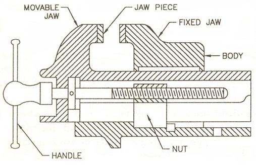
Fig. 2.1 Bench vice
Its specific use is in testing the trueness of a finished surface, testing a try square, providing adequate bearing surface for V-block and angle plates, etc., in scribing work.
It is a cast iron plate having a square or rectangular top perfectly planed true and square with adjacent machined faces. The top is finished true by means of grinding and scrapping. This plate carries a cast iron base under it and the bottom surface of the base is also machined true to keep the top surface of the plate in a perfect horizontal plane.
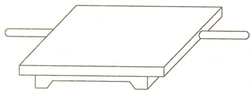
Fig. 2.2 Surface plate
A ‘V” block serves as a very useful support to the work in marking. It usually works in conjunction with a U-clamp.
Round bar is placed longitudinally in the block and the screw in the clamp tightened. Its specific use is in holding the round bars during marking and center drilling their end faces, which are to be held between centers on the lathe. Also it is very suitable for holding round bars in drilling operations when the axis of the drill is to be kept normal to the axis of the bar.
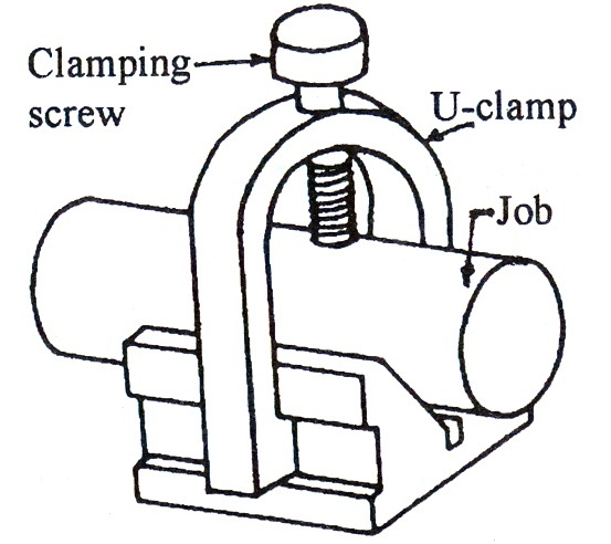
Fig. 2.3 V-Block
2.5 Simple Scribing Block
It is principal marking tool in a fitting shop and is made in various forms and sizes. It consists of a cast iron sliding base fitted with a vertical steel rod. The marker is fitted into an adjustable device carrying a knurled nut at one end. By means of the nut the marker can be loosened or tightened to set it at any desired inclination, moved to and fro inside the hole accommodating it or adjust its height along the vertical pillar. Normally it is used in conjunction with either a surface plate or marking table. Its specific use is in locating centers of round rods held in V-block, describing straight lines on work held firmly in its position by means of a suitable device like angle plate and also in drawing a number of lines parallel to a true surface.
2.6 Universal Surface Gauge
It consists of a cast base, perfectly planed at the top, bottom and all sides. Two guide pins are provided at the rear end of the base which can be pressed down to project below the base. These pins can be used against the edge of the surface plate or any other finished surface for guiding the instrument during scribing.
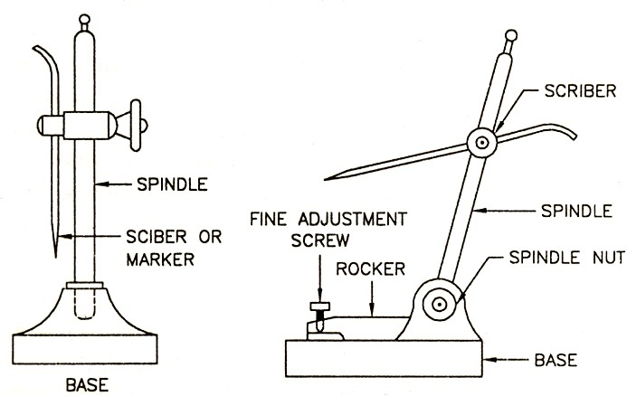
Fig. 2.4 Simple scribing block and universal surface gauge
2.7 Try Square
It is better known as engineer’s try square and is a very common tool used for scribing straight lines at right angles to a true surface or testing the trueness of mutually normal surfaces. They are made in different sizes from the steel pieces.
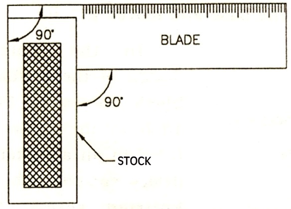
Fig. 2.5 Try square
2.8 Bevel Gauge
Whenever angles other than right angles are required to be tested or set and marked sliding bevel square or bevel gauge is used.
It consists of a steel stock of rectangular cross-section carrying a slotted steel blade at its end. This blade can be made to slide, set at any desired angle and secured in that position by means of a screw.
2.9 Files
Files of different types are the principal hand tools used by a fitter. All the files, irrespective of their shape, size and grade, essentially consist of two main parts, viz., a toothed blade and a pointed tang, which is fitted in a handle. Files are generally forged out of high carbon steel, followed by cutting of teeth, hardening and tempering etc. Common shapes of the files available are flat, hand, square, pillar, round, half round, triangular, knife edge, etc.
These files are manufactured in different varieties and their classification is governed by the following factors: effective length- i.e. excluding the length of tang, shape or form of the cross-section, depth, spacing and cut of teeth
Length of the files varies according to the need but the most commonly used lengths range from 10 cm to 30 cm and they cover almost all sorts of filing work done by hand.
Length between 10 cm and 15 cm are generally used for fine work, between 15 cm and 25 cm for medium sized work and above 25 cm for all general and large sized jobs.
Square file which carried double cut teeth on all the four faces and is normally made tapered for about one-third of its length near the end opposite to the tang.
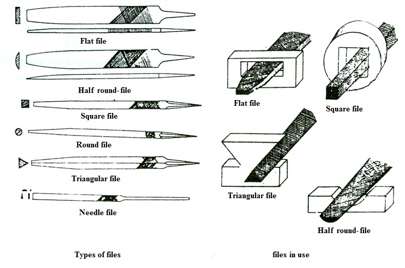
Fig. 2.6 Types of files
Teeth of the files may single cut or double cut. Single teeth are parallel and at angle of 60ºto the center line of the file. Double cut files have two sets of teeth, the overcut teeth are cut at angle of 60º and the uppercut at 75º to 80º to the centre line. Files are also further classified according to the coarseness or spacing between the rows of teeth.
2. Bastard (B) with 18 to 6 cuts per 10 mm length
3. Second cut (SC) with 21 to 11 cuts per 10 mm length
4. Smooth (S) with 30 to 15 cuts per 10 mm length
5. Dead smooth (DS) with 35 to 28 cuts per 10 mm length
6. Super smooth (SS) with 63 to 40 cuts per 10 mm length
2.10 Scrapers
Scraping is a very important hand operation in bench work employed for obtaining a fine surface finish on the work, particularly for removing convex spots from machined surfaces, and the tools used for doing this operation are known as scrapers.
They vary in shape and size, depending upon the specific work for which they are employed.
They are usually made from rejected old files. Such files are heated and bent to the desired shape. They are fitted with a wooden handle.
2.11 Chisels
There are many verities of chisels used for chipping work by a fitter. Some very commonly used forms are Flat, Cross-cut, Round nose and Diamond point.
All the chisels are forged from bar stock of carbon steel, to the desired shape and the cutting edge ground to the correct angle.
The forging operation is followed by annealing, hardening and tempering to make chisel body tough and obtain a sharp cutting edge.
Full length of the chisel is never hardened, only a small length about the cutting edge (say about 20 to 30 mm) is hardened.
The included angle at the cutting edge varies between 40 and 70, depending upon the material on which it is to be used. Approximate values of cutting angles for common materials are as follows:
Brass and copper 40
Wrought iron 50
Cast iron and general cutting work 60
Steel (cast) 70
A flat chisel is a general purpose chisel which is most widely used in cutting work, chipping large surface, cutting metal sheets, rods, bar stocks and similar other purposes. Since it cuts the metal in cold state it is also frequently known as cold chisel.
A round nose chisel is used for drawing the eccentric hold back to correct centre which has run off-centre during drilling operation. Another specific use of this type of chisel is in cutting oil grooves and channels in bearings and pulley bushes and cleaning small round corners.
A cross cut is a comparatively narrow chisel having its cutting edge slightly broader than the blade. It is made to keep the blade free when the chisel is used to cut deep groove into the metal. Normal widths of the cutting edge vary from 3 mm to 12 mm. This chisel is used to cut parallel grooves on large surfaces, before chipping by means of a flat chisel, cutting key ways, etc.
A diamond point chisel is a special purpose chisel used for chipping rough plates and cutting cast iron pipes, cutting ‘V’ grooves, chipping sharp corners, squaring up corners of previously cut slots and cleaning angles.
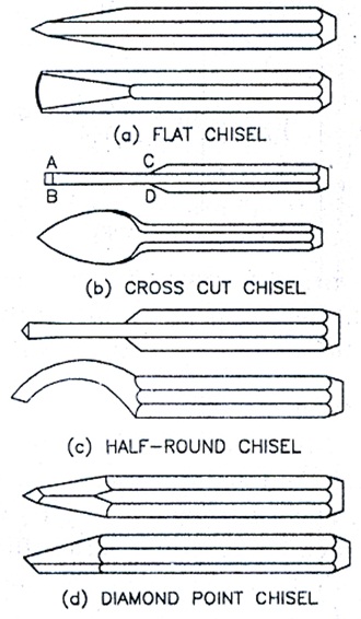
Fig. 2.7 Types of chisel
2.12 Hammers
The hammer is one of the most widely used fitter’s tools. It is used for striking chisels in chipping and cutting and the punch in marking.
All the hammers used in a fitting shop are similar in construction to the smith’s hand hammers, such as ball peen, cross peen, straight peen, etc. The only difference lies in weight. Hammers used in fitting work are comparatively lighter in weight than the smith’s hand hammers. They normally weigh from 0.45 kg to 0.7 kg.
Ball peen hammer is the most commonly used hammer. The peen is ball shaped. It is used for riveting, chipping, drawing and laying out. The weight of the hammer varies from 0.11 to 0.91 kg (as per IS standards)..
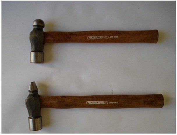
Fig. 2.8 Hammers
Cross peen hammer resembles the ball peen hammer in shape except that its peen is in wedge shape and at right angles to the eye. This hammer is used for bending and hammering in the corners.
Straight peen hammer has a peen in line with the handle and is used for peening or stretching the metal.
2.13 Hack-Saw
Desired lengths of bar stocks, rods, tubes, iron flats and metal sheets, etc. are always required to be cut in fitting shop. Hack-saw is a common tool used for this purpose. It consists of a metal frame, fitted with a wooden handle, carrying metal clips with wing-nut at its end to hold. The clip carrying the wing nut is threaded so as to stretch the blade to the desired extent. The frame can be either of fixed type, which can accommodate the same length of blades or adjustable type which is capable of accommodating different lengths of blades.
Hack saw blades are made of high carbon steel or low alloy steel. Hack saw blade is the main part. Push type blades, those which cut in forward stroke only, are generally used. In these, the teeth always point away from the operator. The blades in common use are generally 0.7 mm thick, 12.7 mm wide and 20 cm to 30 long. About 5 to 7 teeth per cm length of blade from the course group and 8 to 12 teeth per cm from the fine group of teeth.
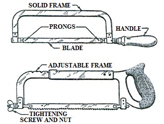
Fig. 2.9 Different parts of a hack saw