Site pages
Current course
Participants
General
20 February - 26 February
27 February - 5 March
6 March - 12 March
13 March - 19 March
20 March - 26 March
27 March - 2 April
3 April - 9 April
10 April - 16 April
17 April - 23 April
24 April - 30 April
Lesson 10. INTRODUCTION TO LATHE MACHINE
Lesson 10
INTRODUCTION TO LATHE MACHINE
10.1 Introduction
The main function of a lathe is to remove metal from a piece of work to give it the required shape and size.This is accomplished by holding the work securely and rigidly on the machine and then turning it against a cutting tool which will remove metal from the work in the form of chips.
10.2 Types of Lathes
1. Speed lathe 5. Tool room lathe
2. Engine lathe 6. Special purpose lathe
3. Bench lathe 7. NC and CNC lathe
4. Production lathe (Automatic lathe, capstan and turret lathe)
10.2.1 Speed lathe
A speed lathe derives its name from the fact that very high spindle speeds are used in this machine. This is the simplest of all lathes.
It consists of a bed supported on legs, a head stock, a tail stock and an adjustable slide for supporting the tool. There is no feed box, carriage or lead screw.
The workplace is held between centres or attached to the face plate.It may be driven from a variable speed motor. The tool is fed and controlled by hand while being supported on the tool slide.
The speed lathe is used principally for turning of wood for small cabinet work.
10.2.2 Engine lathe
Engine lathe is the most important member of the lathe family and the most commonly used. This lathe differs from a speed lathe in that a much larger number of speed steps are available on this machine.
The power to the engine lathe spindle may be given with the help of a belt drive from an overhead line shaft but most modern machines have a captive motor with either a cone pulley drive or an all geared head stock arrangement. The work piece may be supported between centres. The tools are held generally in the tool post on the carriage but sometimes in the tail stock.
10.2.3 Bench lathe
It is a small lathe that is mounted on a work bench. It is used for small work pieces having a maximum swing of 250 mm at the face plate. Lathes of this type are used for precision work on small parts for instrument making.
10.2.4 Production lathe
Production lathes are machines designed to produce large number of duplicate parts faster and with less skill and labour. They employ faster work holding devices and may have two or more tools operating simultaneously. The supervision is simplified and much less skill is needed except for setting the machine. These machines may also be made partially or fully automatic with the operator being needed only for loading the bar stock and removing the finished workpieces. Depending upon the complexity, production lathes may be divided into automatic lathes, capstan and turret lathes.
10.3 Lathe Construction
The machine essentially consists of the following major units:
- Bed
- Head stock
- Tall stock
- Carriage assembly

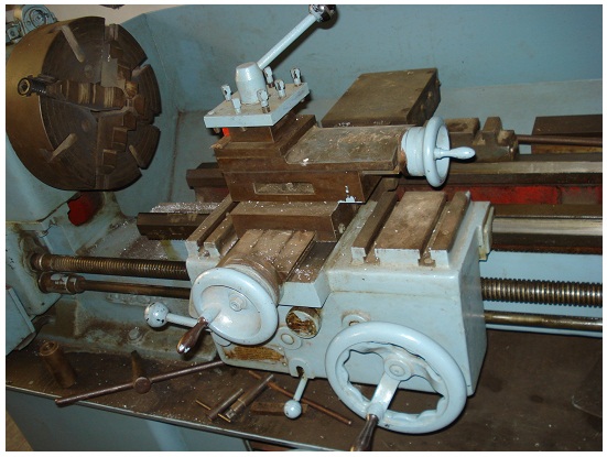
Fig. 10.1 A geared-head lathe
The bed of the lathe forms the base of the machine. It is supported on two legs at a convenient height. It carries the head stock and the tail stock for supporting the work and provides a base for the movement of the carriage assembly which carries the tool.
To ensure accurate machining work it is necessary that the bed has enough rigidly and torsional stiffness to withstand the action of cutting forces.
The bed of the lathe is sometimes made with a small gap in front of the head stock to accommodate short jobs which need a swing larger than that available on the rest of the bed.
10.3.2 Head stock
The head stock houses the spindle and the means for supporting and rotating the spindle. It is rigidly fixed on the bed. The spindle which is made of steel is made hollow so that long bars which are being machined at the end may pass through it. The right hand end of the spindle which projects out of the head stock body has a threaded outside and a tapered bore. For turning between centres a carrier plate may be mounted on the threaded end. In larger lathes instead of the threaded end, a flange is provided over which the dog plate, chuck or face plate as the case may be, are located and bolted. The tapered end and the hollow spindle also permit mounting of a draw-in collect chuck when designed.
10.3.3 Tail stock
The tail stock is for the purpose of primarily giving an outer bearing, support for work being turned on centres. It can be adjusted for alignment or non-alignment with respect to the spindle centre and carries a centre called dead centre for supporting one end of the work. Both live and dead centres have 60 conical points to fit centre holes in the work, the other end tapering to allow for good fitting into the spindles. Now-a-days, the dead centre is mounted in ball bearing so that it rotates with the job avoiding friction of the job with dead centre. This is specially necessary with heavy jobs.
10.3.4 Carriage Assembly
The carriage assembly of the lathe comprises of a number of components which support, move and control the tool. The carriage assembly consists of a saddle, cross slide, compound rest, top slide, tool post and apron. Movement of the entire carriage assembly along the bed provides feed for the tool parallel to the lathe axis: movement of the cross slide along its guides on the saddle provides feed of the tool across the lathe axis and the movement of the top slide along its guide over the compound rest provides motion to the tool along a direction set by the compound rest. The movement of the carriage and cross slide may be by hand or by power but the movement of top slide is only by hand.

Fig. 10.2 Carriage assembly
10.3.5 Lathe accessories
Lathe accessories include centres, catch plates and carriers, chucks, face plates, angle plates,mandrels, and rests. They are used either for holding and supporting the work or for holding the tool.
Lathe centres: The most common method of holding the work in a lathe is between the two centres –live centre and dead centre. They are made of very hard materials to resist deflection and wear.
Carriers and catch plates: Carriers and catch plates are used to drive a work piece when it is held between two centres.
Chucks: A chuck is one of the most important devices for holding and rotating a piece of work in a lathe. Work pieces of short length, and large diameter or of irregular shape which cannot be conveniently mounted between centres are held quickly and rigidly in a chuck.
The different types of chucks are :
(1) Four jaw independent chuck 4. Magnetic chuck
(2) Three jaw universal chuck 5 Drill chuck
(3) Combination chuck
10.4 Lathe operations
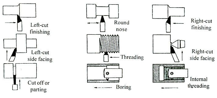
With suitable attachments and modifications a lathe can be made to perform any machining operation done on a number of general purpose machines. Operations commonly performed on a lathe include turning, facing, form turning, grooving, drilling,boring, knurling, taper turning and thread cutting.
10.4.1 Turning
Turning is the operation in which a cylindrical surface is produced. The work piece is supported between centres or in any other work holding device, and rotated at the desired speed. The tool is first given a depth of cut by using the cross slide motion of the carriage and then given an axial feed by hand or power. Which can be made to overlap to produce a cylindrical surface on the work piece by adjusting the feed and having a large nose radius. Repeated cuts may be necessary to obtain a desired reduction of size. A final finishing cut may be given to the work piece with low depth of cut and feed but high speed to attain the desired degree of surface finish.
10.4.2 Facing
Facing is an operation used to produce a flat surface at right angles to the rotational axis of the job. In this case tool is fed at right angles to the job while the depth of cut is provided by the axial motion of the carriage. The job may be held in a chuck or between centres. In this centre about half of the front cone is removed to give access to the tool.
10.4.3 Drilling
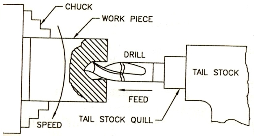
The work piece is held in a chuck or on a face plate and the drill is held in the tail stock quill or in a drill chuck held in the quill. The taper in the quill ensures that the axis of the drill is concentric with the rotational axis of the spindle. Feeding is done by movement of the tail stock quill. Reamers, counter bores and other cutting tools may also be used similarly in place of drill.

Fig. 10.3 Drilling operation
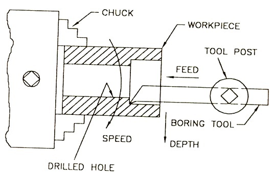
10.4.4 Boring

Fig. 10.4 Boring operation
10.4.5 Knurling
Knurling is the process of embossing a diamond shaped pattern on the cylindrical surface of a work piece. Knurling is done on the work piece so that it does not slip when held and operated by hand. The work piece is supported in the chuck but since quite heavy forces are involved in the knurling process an additional support is generally provided at the free end with the tail stock centre. Knurling is done with two serrated hardened steel rollers pressing into the work piece. (Fig. 10.5)
The roller serrations are at 45 degrees to the horizontal but 90degrees to each other so that a diamond shaped pattern is produced by amechanical working process. No cutting is involved in the knurling process. Acomplete knurling tool head consists of three pairs of knurling rollers withdifferent depth and spacing of serrations to give fine, medium and coarse knurling.
10.4.6 Taper turning
Taper turning isthe process of producing external and internal conical surfaces by combiningthe rotation of the job and the relative angular feed of the tool. Tapers areused on many tools and machine components for alignment and for easy holding. Suchas the shank of twist drills, end mills and reamers, spindles of lathe anddrilling machine.
Thread cutting

Fig. 10.6 Lathe operation