Site pages
Current course
Participants
General
MODULE 1. FLUIDS MECHANICS
MODULE 2. PROPERTIES OF FLUIDS
MODULE 3. PRESSURE AND ITS MEASUREMENT
MODULE 4. PASCAL’S LAW
MODULE 5. PRESSURE FORCES ON PLANE AND CURVED SUR...
MODULE 6.
MODULE 7. BUOYANCY, METACENTRE AND METACENTRIC HEI...
MODULE 8. KINEMATICS OF FLUID FLOW
MODULE 9: CIRCULATION AND VORTICITY
MODULE 10.
MODULE 11.
MODULE 12, 13. FLUID DYNAMICS
MODULE 14.
MODULE 15. LAMINAR AND TURBULENT FLOW IN PIPES
MODULE 16. GENERAL EQUATION FOR HEAD LOSS-DARCY EQ...
MODULE 17.
MODULE 18. MAJOR AND MINOR HYDRAULIC LOSSES THROUG...
MODULE 19.
MODULE 20.
MODULE 21. DIMENSIONAL ANALYSIS AND SIMILITUDE
MODULE 22. INTRODUCTION TO FLUID MACHINERY
LESSON 19. APPLICATIONS OF BERNOULI’S EQUATION
Physical interpretation of Bernoulli equation
- Integration of the equation of motion to give the Bernoulli equation actually corresponds to the work-energy principle often used in the study of dynamics.
-
This principle results from a general integration of the equations of motion for an object in a very similar to that done for the fluid particle.
-
With certain assumptions, a statement of the work-energy principle may be written as follows:
-
The work done on a particle by all forces acting on the particle is equal to the change of the kinetic energy of the particle.
-
The Bernoulli equation is a mathematical statement of this principle.
-
In fact, an alternate method of deriving the Bernoulli equation is to use the first and second laws of thermodynamics (the energy and entropy equations), rather than Newton’s second law. With the approach restrictions, the general energy equation reduces to the Bernoulli equation.
An alternate but equivalent form of the Bernoulli equation is:
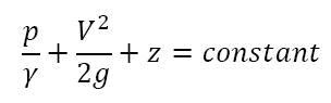
Along a streamline:
Pressure head:
![]()
Velocity head:
![]()
Elevation head:
Z
The Bernoulli equation states that the sum of the pressure head, the velocity head, and the elevation head is constant along a streamline.
Static, Stagnation, Dynamic, and Total Pressure
Along a streamline:
Static pressure:
ρ
Dynamic pressure:

Hydrostatic pressure:
YZ
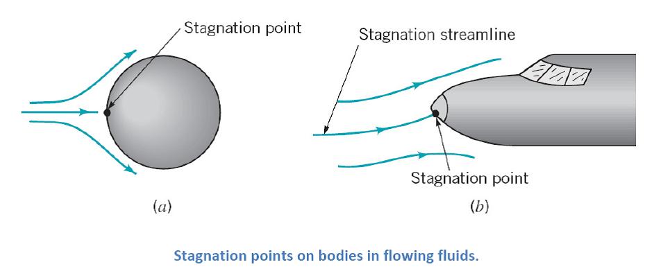
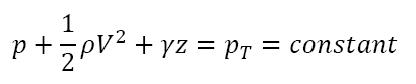
Stagnation pressure:
![]()
(assuming elevation effects are negligible) where p and V are the pressure and velocity of the fluid upstream of stagnation point. At stagnation point, fluid velocity V becomes zero and all of the kinetic energy converts into a pressure rise.
Total pressure:
![]()
(along a streamline)
Applications of Bernoulli Equation
1) Stagnation Tube
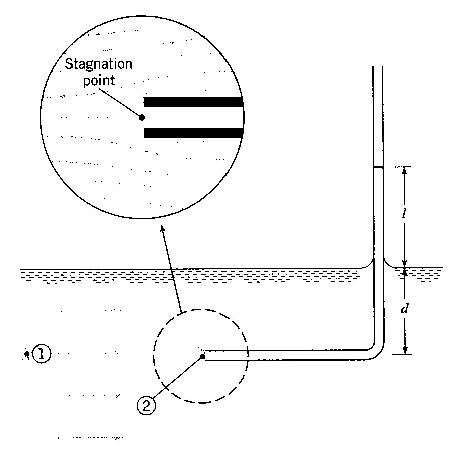
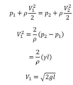
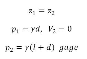
Limited by length of tube and need for free surface reference
2) Pitot Tube
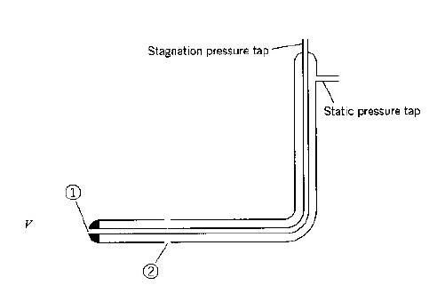

where,
V1 = 0 and h = piezometric head
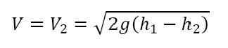
h1 - h2
from manometer or pressure gage
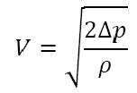
For gas flow
![]()

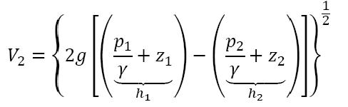
Application of Bernoulli equation between points (1) and (2) on the streamline
shown gives
![]()
![]()
![]()

Bernoulli equation between points (1) and (5) gives
![]()
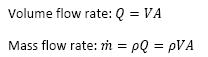
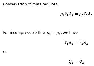
3) Simplified form of the continuity equation
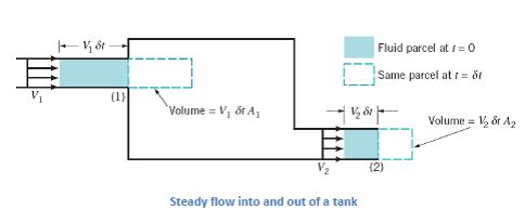
Obtained from the following intuitive arguments:
Last modified: Monday, 16 September 2013, 6:54 AM