Site pages
Current course
Participants
General
MODULE 1. FLUIDS MECHANICS
MODULE 2. PROPERTIES OF FLUIDS
MODULE 3. PRESSURE AND ITS MEASUREMENT
MODULE 4. PASCAL’S LAW
MODULE 5. PRESSURE FORCES ON PLANE AND CURVED SUR...
MODULE 6.
MODULE 7. BUOYANCY, METACENTRE AND METACENTRIC HEI...
MODULE 8. KINEMATICS OF FLUID FLOW
MODULE 9: CIRCULATION AND VORTICITY
MODULE 10.
MODULE 11.
MODULE 12, 13. FLUID DYNAMICS
MODULE 14.
MODULE 15. LAMINAR AND TURBULENT FLOW IN PIPES
MODULE 16. GENERAL EQUATION FOR HEAD LOSS-DARCY EQ...
MODULE 17.
MODULE 18. MAJOR AND MINOR HYDRAULIC LOSSES THROUG...
MODULE 19.
MODULE 20.
MODULE 21. DIMENSIONAL ANALYSIS AND SIMILITUDE
MODULE 22. INTRODUCTION TO FLUID MACHINERY
LESSON 25. GENERAL EQUATION FOR HEAD LOSS-DARCY EQUATION
Flow of fluid through a pipe
-
Head loss is the reduction in the total head or pressure (sum of elevation head, velocity head and pressure head) of the fluid as it moves through a fluid system.
-
Head loss is unavoidable in real fluids. It is present because of:
-
the friction between the fluid and the walls of the pipe;
-
the friction between adjacent fluid particles as they move relative to one another; and
-
the turbulence caused whenever the flow is redirected or affected in any way by such components as piping entrances and exits, pumps, valves, flow reducers, and fittings.
-
-
Frictional loss is that part of the total head loss that occurs as the fluid flows through straight pipes.
-
The head loss for fluid flow is directly proportional to the length of pipe, the square of the fluid velocity, and a term accounting for fluid friction called the friction factor.
-
The head loss is inversely proportional to the diameter of the pipe.
Pressure Pipe Flow
Refers to full water flow in closed conduits of circular cross sections under a certain pressure gradient. For a given discharge (Q), pipe flow at any location can be described by the pipe cross section, the pipe elevation, the pressure, and the flow velocity in the pipe.
Elevation (h)
of a particular section in the pipe is usually measured with respect to a horizontal reference datum such as mean sea level (MSL).
Pressure (P)
in the pipe varies from one point to another, but a mean value is normally used at a given cross section.
Mean velocity (V)
is defined as the discharge (Q) divided by the cross-sectional area (A)

Loss of Head From Pipe Friction
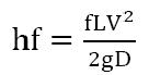
Energy loss resulting from friction in a pipeline is commonly termed the friction head loss(hf). This is the loss of head caused by pipe wall friction and the viscous dissipation in flowing water. It is also called major loss.
The most popular pipe flow equation was derived by Henry Darcy (1803 to 1858), Julius Weiscbach (1806 to 1871), and the others about the middle of the nineteenth century. The equation takes the following form and is commonly known as the
Darcy-Weisbach Equation.
When Reynolds Number (NR) is less than 2000 flow in the pipe is laminar and friction factor is calculated with the following formula;

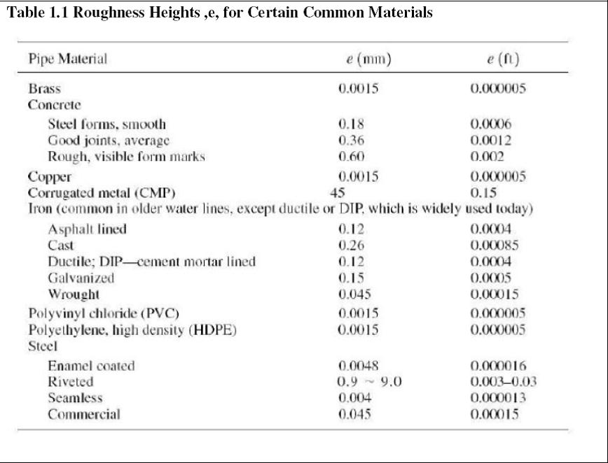
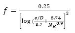
When Reynolds Number (NR) is greater or equal to 2000, the flow in the pipe becomes practically turbulent and the value of friction factor (f) then becomes less dependent on the Reynolds Number but more dependent on the relative rougness (e/D) of the pipe. The roughness height for certain common commercial pipe materials is provided in Table 1.1.
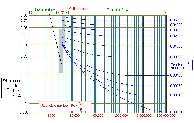
Friction factor can be found in three ways:
1. Graphical solution: Moody Diagram
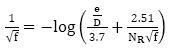
2. Implicit equations : Colebrook-White Equation
3. Explicit equations: : Swamee-Jain Equation
1. Graphical solution: Moody Diagram
2. Implicit equations : Colebrook-White Equation
3. Explicit equations : Swamee-Jain Equation
Last modified: Tuesday, 8 October 2013, 9:52 AM