Site pages
Current course
Participants
General
MODULE 1.
MODULE 2.
MODULE 3.
MODULE 4.
MODULE 5.
MODULE 6.
MODULE 7.
MODULE 8.
MODULE 9.
MODULE 10.
MODULE 11.
MODULE 12.
MODULE 13.
MODULE 14.
MODULE 15.
MODULE 16.
MODULE 17.
MODULE 18.
MODULE 19.
LESSON 20. Counters-Asynchronous and synchronous counter-decade counter-up down counter- ring and Johnson counter.
COUNTER
Electronic counters:
In electronics, counters can be implemented quite easily using register-type circuits such as the flip-flop, and a wide variety of classifications exist:
-
Asynchronous (ripple) counter – changing state bits are used as clocks to subsequent state flip-flops
-
Synchronous counter – all state bits change under control of a single clock
-
Decade counter – counts through ten states per stage
-
Up/down counter – counts both up and down, under command of a control input
-
Ring counter – formed by a shift register with feedback connection in a ring
-
Johnson counter – a twisted ring counter
-
Cascaded counter
Each is useful for different applications. Usually, counter circuits are digital in nature, and count in natural binary. Many types of counter circuits are available as digital building blocks, for example a number of chips in the 4000 series implement different counters.
Occasionally there are advantages to using a counting sequence other than the natural binary sequence such as the binary coded decimal counter, a linear feedback shift register counter, or a Gray-code counter.
Counters are useful for digital clocks and timers, and in oven timers, VCR clocks, etc.
Counters
The function of a counter is to count the number of clock pulses, which have arrived at the clock input. A counter consists of a number of flip-flops. Counters are classified as ripple counter (or asynchronous counter) and synchronous counter.
Ripple Counter
Figure shows the circuit of a 4-bit ripple counter consisting of 4 –edge triggered JK flip-flop. As indicated by small circles at the CLK input of flip-flop, the triggering occurs when CLK input gets a negative edge. Q is the least significant bit (LSB) and Q is the most significant bit (MSB). The flip-flops are connected in series. The Q output is connected to CLK terminal of second flip-flop.
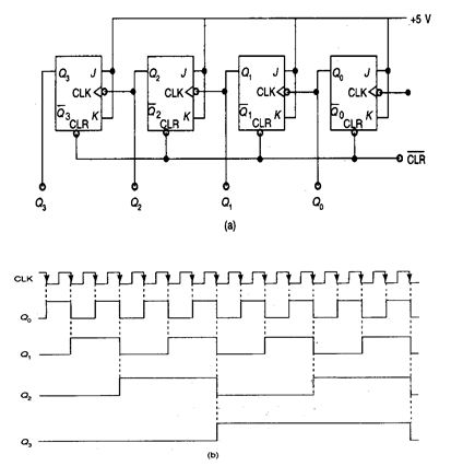
The Q output is connected to CLK terminal of third flip-flop and so on. By adding more flip-flops a counter of any length can be built. It is know as a ripple counter because the carry moves through the flip-flops like a ripple on water. Initially, CLR is made low and all flip-flops reset giving an output Q =0000. When CLR becomes high, the counter is ready to start. As LSB receives its clock pulse, its output changes from 0 to1 and the total ouptu Q = 0001. When second clock pulse arrives, Q resets and carries (i.e., Q goes from 1 to 0 and the second flip flop will receive CLKK input). Now the output is Q = 0010. The third CLK pulse changes Q to 1 giving a total output Q = 0100 and the process goes on. The number of output states of a counter is known as modulus (or mod). A ripple counter with 4 flip-flops can count from 0-15 and is , therefore, known as mod-16 counter while one with 6 flip-flops can count from 0 to 63 and is a mod-64 counter and so on.
Ripple counters are simple to fabricate but have the problem that the carry has to propagate through a number of flip-flops. The delay; time of all the flip-flops are added. Therefore, they are very slow for some applications. Another problem is that unwanted pulses occur at the output of gates.
Synchronous Counter
In a synchronous counter, all the flip-flops are clocked together. Figure 8.36 shows a synchronous counter having positive edge triggered JK flip-flops. Since all the flip-flops are clocked together, the delay time is less. The flip-flop corresponding to least significant bit (LSB) has its inputs J K fed from voltage + V. Therefore, it responds to each positive clock edge. However, the other three flip-flops can respond to the positive clock pulse.
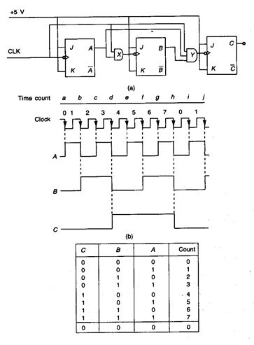
under some certain conditions. The Q flip-flop toggles on positive clock edge only if Q is 1. The Q flip-flop toggles on positive clock edge only when Q and Q are 1 (due to presence of AND circuit) and so on.
Thus, each flip-flop toggles on the next positive clock edge if all lower bits are 1.
A low (CLR) signal resets the counter so that Q=0000. When CLR goes high, the counter is ready to start. The first positive clock edge sets Q to 1 so that Q=0001. At second positive clock edge Q and Q toggle and Q=0010. The third positive clock edge increases the count by 1 so that Q =0011.
The successive Q outputs are 0100, 0101 and so on upto 1111 (i.e., decimal 15). The next positive clock edge resets the counter to 000 and the cycle is repeated. More flip-flops can be added to increase the count.
RING COUNTER
The following figure is the circuit of a ring counter. It uses D flip-flops. The output Q sets D input, Q sets D, Q sets D and Q is fed back to D. Because of these connections, bits are shifted left one position per positive clock edge and fed back to the input. As seen, all the flip-flops are clocked together.
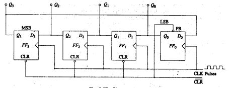
When CLR goes low then back to high, the output is Q=0000. The first positive clock edge shifts MSB to LSB position and other bits to one position left so that the output becomes Q = 0010. This process continues on second and third positive clock edge so that successive outputs are 0100 and 1000. The fourth positive clock edge starts the cycle all over again and output Q=0001. Thus, the stored 1 bits follow a circular path (i.e., the stored 1 bits move left through all flip-flops and the final flip flop sends it back to the first flip-flop. This action has given it the name of ring counter. It is used to control a sequence of operations in a sequence, control stepper motors
USES:
The use of flip-flop outputs as clocks leads to timing skew between the count data bits, making this ripple technique incompatible with normal synchronous circuit design styles.
Synchronous counter:
A 4-bit synchronous counter using JK flip-flops. A simple way of implementing the logic for each bit of an ascending counter (which is what is depicted in the image to the right) is for each bit to toggle when all of the less significant bits are at a logic high state. For example, bit 1 toggles when bit 0 is logic high; bit 2 toggles when both bit 1 and bit 0 are logic high; bit 3 toggles when bit 2, bit 1 and bit 0 are all high; and so on.Synchronous counters can also be implemented with hardware finite state machines, which are more complex but allow for smoother, more stable transitions. Hardware-based counters are of this type.
DECADE COUNTER:
A decade counter is one that counts in decimal digits, rather than binary. A decade counter may have each digit binary encoded (that is, it may count in binary-coded decimal, as the 7490 integrated circuit did) or other binary encodings (such as the bi-quinary encoding of the 7490 integrated circuit).
Alternatively, it may have a "fully decoded" or one-hot output code in which each output goes high in turn (the 4017 is such a circuit). The latter type of circuit finds applications in multiplexers and demultiplexers, or wherever a scanning type of behavior is useful. Similar counters with different numbers of outputs are also common.
The decade counter is also known as a mod-counter when it counts to ten (0, 1, 2, 3, 4, 5, 6, 7, 8, 9). A Mod Counter that counts to 64 stops at 63 because 0 counts as a valid digit.
UP/DOWN COUNTER:
A counter that can change state in either direction, under the control of an up/down selector input, is known as an up/down counter. When the selector is in the up state, the counter increments its value. When the selector is in the down state, the counter decrements the count.
RING COUNTER:
A ring counter is a circular shift register which is initiated such that only one of its flip-flops is the state one while others are in their zero states.
A ring counter is a Shift Register (a cascade connection of flip-flops) with the output of the last one connected to the input of the first, that is, in a ring. Typically, a pattern consisting of a single bit is circulated so the state repeats every n clock cycles if n flip-flops are used. It can be used as a cycle counter of n states.
Johnson counter:
A Johnson counter (or switchtail ring counter, twisted-ring counter, walking-ring counter, or Moebius counter) is a modified ring counter, where the output from the last stage is inverted and fed back as input to the first stage.[2][3][4] The register cycles through a sequence of bit-patterns, whose length is equal to twice the length of the shift register, continuing indefinitely.
These counters find specialist applications, including those similar to the decade counter, digital-to-analog conversion, etc. They can be implemented easily using D- or JK-type flip-flops.
Computer science counters
In computability theory, a counter is considered a type of memory. A counter stores a single natural number (initially zero) and can be arbitrarily many digits long.
A counter is usually considered in conjunction with a finite-state machine (FSM), which can perform the following operations on the counter:
-
Check whether the counter is zero
-
Increment the counter by one.
-
Decrement the counter by one (if it's already zero, this leaves it unchanged).
The following machines are listed in order of power, with each one being strictly more powerful than the one below it:
-
Deterministic or non-deterministic FSM plus two counters
-
Non-deterministic FSM plus one stack
-
Non-deterministic FSM plus one counter
-
Deterministic FSM plus one counter
-
Deterministic or non-deterministic FSM
For the first and last, it doesn't matter whether the FSM is a deterministic finite automaton or a nondeterministic finite automaton. They have equivalent power. The first two and the last one are levels of the Chomsky hierarchy.
Last modified: Thursday, 5 December 2013, 7:47 AM