Site pages
Current course
Participants
General
MODULE 1.
MODULE 2.
MODULE 3.
MODULE 4.
MODULE 5.
MODULE 6.
MODULE 7.
MODULE 8.
MODULE 9.
MODULE 10.
MODULE 11.
MODULE 12.
MODULE 13.
MODULE 14.
MODULE 15.
MODULE 16.
MODULE 17.
MODULE 18.
MODULE 19.
LESSON 31. Strain gauge-metallic sensing elements-Unbonded strain gauges-problem associated with strain gauge installation. Type of strain gauge.
STRAIN GAGE
The strain gage is an example of a passive transducer that converts a mechanical displacement into a change of resistance. A strain gage is a thin, wafer-like device that can be attached (bonded) to a variety of materials to measure applied strain. Metallic strain gages are manufactured from small diameter resistance wire, such as Constantan, or etched from thin foil sheets. The resistance of the wire or metal foil changes with length as the material to which gage is attached undergoes tension or compression. This change in resistance is proportional to the applied strain and is measured with a specially adapted Wheat-stone bridge.
The sensitivity of a strain gage is described in terms of a characteristic called the gage factor, K, defined as the unit change in resistance per unit change in length, or
gage factor K 
where K = gage factor
R = nominal gage resistance
DR = change in gage resistance
l = normal specimen length (unstressed condition)
Dl = change in specimen length
The term Dl/l in the denominator of Eq.(11-1) is the strain s, so that Eq.(11-1) can be written as

where s is the strain in the lateral direction.
The resistance change DR of a conductor with length l can be calculated by using the expression for the resistance of a conductor of uniform cross section :
Length p x l
R = p ----------- = ---------
Area (π/4)d2
Where p = specific resistance of the conductor material
l = length of the conductor
d = diameter of the conductor
Tension on the conductor causes an increase Dl in its length and a simultaneous decrease Dd in its diameter. The resistance of the conductor then changes to
(l + Δl) l(l + Δl/l)
RS = p ----------------- = p------------------------
(π/4)(d-Δd)2 (π/4)d2 (1-2Δd/d)
Equation ---- may be simplified by using Poisson’s ratio, µ, defined as the ratio of strain in the lateral direction to strain in the axial direction. Therefore,
Δd/d
µ = ----------
Δl/l
substitution yields
l (l + Δl/l)
RS = p ----------------- (-----------------
(π/4)d2 (1-2µ Δl/l)
which can be simplified to
RS = R + ΔR = R [1+(1+2µ)Δl/l]
The increment of resistance DR as compared to the increment of length Dl can then be expressed in terms of the gage factor K where
ΔR/R
K = ----------- = 1 + 2µ
Δ l/l
Poissons’ ratio for most metals lies in the range of 0.25 to 0.35, and the gage factor would then be on the order of 1.5 to 1.7.
For strain gage applications, a high sensitivity is very desirable. A large gage factor means a relatively large resistance change, which can be more easily measured than a small resistance change. For Constantan wire, K is about 2, whereas Alloy 479 gives a K value of about 4.It is interesting carry out a simple calculation to find out what effect an applied stress has on the resistance change of a strain gage. Hooke’s law gives the relationship between stress and strain for a linear stress strain curve, in terms of the modulus of elasticity of the material under tension. Defining stress as the applied force per unit area and strain as the elongation of the stressed member per unit length, Hooke’s law is written as
S
σ = --
E
Where s =strain, Δl/l (no units)
S = stress (kg/cm2)
E = Young’s modulus (kg/cm2)
Metallic sensing elements
Metallic strain gages are formed from thin resistance wire or etched from thin sheets of metal foil. 1. Wire gages are generally small in size, are subject to minimal leakage, and can be used in high temperature applications. 2. Foil elements are somewhat larger in size and are more stable than wire gages. They can be used under extreme temperature conditions and under prolonged loading, and they dissipate self-induced heat easily.
Various resistance materials have been developed for use in wire and foil gages. Some of these are described in the following paragraphs.
Constantan is a copper-nickel alloy with a low temperature coefficient. Constantan is commonly found in gages that are used in dynamic strain measurements, where alternating strain levels do not exceed ± 1,500 µcm/cm. Operating temperature limits are from 10°C to 200°C.
Nichrome V is a nickel-chrome alloy used for static strain measurements to 375°C. with temperature compensation, the alloy may be used for static measurements to 650°C and dynamic measurements to 1000°C.
Dynaloy is a nickel-iron alloy with a high gage factor and a high resistance to fatigue. This material is used in dynamic strain applications when high temperature sensitivity can be tolerated. The temperature range of dynaloy gages is generally limited by the carrier materials and the bonding cement.
Stabiloy is a modified nickel-chrome alloy with a wide temperature compensation range. These gages have excellent stability from cryogenic temperatures to approimately 350°C and good fatigue life.
Platinum tungsten alloys offer excellent stability and high resistance to fatigue at elevated temperatures. These gages are recommended for static tests to 700°C and dynamic measurements to 850°C. because the material has a relatively large temperature coefficient, some form of temperature compensation must be used to correct this error.
Semiconductor strain gages are often used in high-output transducers such as load cells. These gages have very high sensitivities, with gage factors from 50 to 200. They are, however, sensitive to temperature fluctuations and often behave in a nonlinear manner.
The size of the finished gage, and the manner in which the wire or foil pattern is arranged, varies with the application. Some bonded gages can be as small as 1/8 in by 1/8 in., although they are generally somewhat larger, and are manufactured to a maximum size of 1 in. long by ½ in. wide. In the usual application, the strain gage is cemented to the structure whose strain is to be measured. The problem of providing a good bonding between the gage and the structure is very difficult. The adhesive material must hold the gage firmly to the structure, yet it must have sufficient elasticity to give under strain without losing its adhesive properties. The adhesive should also be resistant to temperature, humidity and other environmental conditions.
Gage configuration
The shape of the sensing element is selected according to the strain to be measured : uniaxial, biaxial, or multidirectional. Uniaxial applications most often use long, narrow sensing elements, as in fig. To maximize the strain sensing material in the direction of interest. End loops are few and short, so that sensitivity to transverse strains is low. Gage length is selected according to the strain field to be investigated. For most strain measurements, the 6mm gage length offers good performance and easy installation.
Simultaneous measurement of strains in more than one direction can be accomplished by placing single-element gages at the proper locations. However, to simplify this task and provide greater accuracy, multielement, or rosette, gages are available.
Two-element rosettes, shown in fig, are often used in force transducers. The gages are wired in a Wheatstone bridge circuit to provide maximum output. For stress analysis, the axial and transverse elements may have different resistances that can be so selected that the combined output is proportional to stress while the output of the axial element alone is proportion to strain. Three element rosettes are often used to determine the direction and magnitude of principal strains resulting from complex structural loading. The most popular types have 45° - or 60°-angular displacements between the sensing elements, as shown in fig. The 60° rosettes are used when the direction of the principal strains is unknown. The 45° rosettes provide greater angular resolutions and are normally used when the directions of the principal strains are known.
Unbonded strain gage
The unbonded straing gage consists of a stationary frame and an armature that is supported in the centre of the frame. The armature can move only in one direction. Its travel in that direction is limited by four filaments of strain sensitive wire, wound between rigid insulators that are mounted on the frame and on the armature. The filaments are of equal length and arranged as shown in fig.
When an external force is applied to the strain gage, the armature moves in the direction indicated. Elements A and D increase in length, whereas elements B and C decrease in length. The resistance change of the four filaments is proportional to their change in length, and this change can be measured with a Wheat-stone bridge, as shown in fig. The unbalance current, indicated by the current meter, is calibrated to read the magnitude of the displacement of the armature.
The unbonded strain gage transducer can be constructed in a variety of configurations, depending on the required use. Its principal use is a displacement transducer. A linkage pin can be attached to the armature in order to measure displacement directly. The unit of Fig. allows an armature displacement of 0.004 cm on each side of its center position. Using the same construction, the unit will functions as a dynamometer, capable of measuring force. Depending on the number of turns and the diameter of the strain wires, the transducer will measure forces from ±40 g to ±2 kg, full scale.
The transducer becomes a pressure pickup when its armature is connected to metallic bellows or diaphragm. When a bellows is used, force on the end of the bellows is transmitted by a pin to the armature, and the unit functions as a dynamometer. By applying pressure to one side of the bellows and venting the other side to the atmosphere, gage pressures may be read. If the bellows is evacuated and sealed, absolute pressure is measured.
Another modification is provided by two pressure connections, one to each side of the bellows or diaphragm, for the measurement of differential pressure.
When strain gages are mounted as a specimen, two notes of cauha should be followed : (1) the surface should be absolutely cleaning with emery cloth followed by acetone is usually satisfactory, (2) Sufficient time must be allowed for the cement to dry and harden completely. Even though the cement is dry around the edge of the gage, it may still be wet under the gage. If possible, 24h should be allowed for drying at room temperature. Drying time may be reduced for higher temperatures.
Several different cements are available for mounting strain gages. These cements are discussed in Ref.(2) alongwith rather detailed instructions for mounting the various types of gages. The interested reader should consult this reference and the literature of various manufacturers of strain gages for more information.
Problems associated with strain-gage installations generally fall into three categories : (1) temperature effects (2) moisture effects and (3) wiring problems. It is assumed that the gage is properly mounted. Temperature problems arise because of differential thermal expansion between the resistance element and the material to which it is bonded. Semiconductor gages offer the advantage that they have a lower expansion coefficient than either wire or foil gages. In addition to the expansion problem, there is a change in resistance of the gage with temperature, which must be adequately compensated for. We shall see how this compensation is performed in a subsequent paragraph. Moisture absorption by the paper and cement can change the electrical resistance between the gage and the ground potential and thus affect the output-resistance readings. Methods of moisture proofing are discussed in Refs. Wiring problems are those situations that arise because of faulty connections between the gage-resistance element and the external readout circuit. These problems may develop from poorly soldered connections or from inflexible wiring, which may pull the gage loose from the test specimen or break the gage altogether. Proper wiring practices are discussed in Res.
Electrical resistance strain gages cannot be easily calibrated because once they are attached to a calibration work piece, removal cannot be made without destroying the gage. In practice, then, the gage factor is taken as the value specified by the manufacturer and a semi calibration effected by checking the bridge measurement and readout system.
In the design and construction of machines and structures, the strength of the material plays a very important role. A theoretical knowledge of this property is essential to estimate whether the mechanical components can carry the loads demanded of them, without excessive deformation or failure. These load-carrying abilities are normally characterized in terms of stress, which is defined as the force experienced per unit area, and is expressed in pressure units. Stress itself cannot be measured directly and is normally deduced from the changes in mechanical dimensions and the applied load. The mechan- ical deformation formed due to stress is measured with strain-gauge elements. The relationship betweer load and elongation is characterized in terms of strain which is defined as the change L1t in length t pel unit length and is expressed as At /t in microstrains.
The precise measurement of the parameter 'strain' is an important aspect in measurement engineering as it is very often encountered in many fields of engineering and technology, especially in experimenta stress analysis. Further, a large number of mechanical and physical parameters can be related witt devices operating on the principle of strain measurement.
The stress to strain relationship in a simple tension or compression test is expressed as linear so long as the stress is kept below the elastic limit.
The deformation of a strut under simple ten- 9 si on loading is given in Fig.. The length is <n increased by L1x and the cross-section is de- creased by L1y x Liz. If the strain is measured either of the planes perpendicular to the applied load, a strain with a lesser magnitude and with opposite sign is developed in this plane and this effect is known as Poisson's effect. The magni- tude is expressed as the Poisson's ratio v which
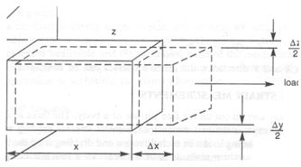
Fig. Deformation of a strut
FACTORS AFFECTING STRAIN MEASUREMENTS
Strain measurements are normally carried out on the free surface of a body. The three strains Ex' E " and El defined in Sec. 5.1 adequately express the two-dimensional state of stresses existing on the surface. By measuring displacements corresponding to 11 x in each direction and dividing it by the original length x, the strain can be determined. The strain magnitude is of the order of a few micrometers per metre expressed as microstrains. But it is difficult to measure such displacements directly, except in certain isolated cases, since the magnitude involved is very small. Therefore, a device or gauge, which can yield surface strains directly, is preferred. Such a device is popularly known as the "strain gauge". An accurate definition of strain on the surface requires the determination of the slopes of the displacement of the surfaces. The strains as such are likely to vary from point to point. Direct measurements of such small displacements over the entire surface of the body are also difficult. This is overcome by measuring one displacement component over a small portion of the body, along a short line segment. The strain measured in this manner may not be the true value, since the measurement is made over a finite length and not at a point. The error produced by this approach depends upon the strain gradient and the length of the line segment.
It is imperative to reduce the size of a strain gauge to improve the accuracy of measurements, but as the size is very much reduced, dimensional tolerances become very critical. If a strain value of the order of 1000 microstrains is to be measured to an accuracy of 5 microstrains over a gauge length of 5 mm, a displacement of 25 x 10-5 mm has to be accurately determined.
The basic characteristics of a strain gauge that one looks for are the gauge length, gauge width, gauge sensitivity, range of measurement, accuracy, frequency response and the ambient environmental conditions it can withstand. Since strain cannot be measured at a point, non-linear stress fields can give rise to errors, depending upon the gauge dimensions. Sensitivity, which is defined as the smallest value of strain that can be read, is of the order of microstrain and can be attained with the aid of modem instrumentation techniques. The maximum strain measurable and the accuracy achievable depends very much upon the type of gauges used and the method of gauging employed.
Last modified: Thursday, 5 December 2013, 9:21 AM