Site pages
Current course
Participants
General
MODULE 1.
MODULE 2.
MODULE 3.
MODULE 4.
MODULE 5.
MODULE 6.
MODULE 7.
MODULE 8.
MODULE 9.
MODULE 10.
MODULE 11.
MODULE 12.
MODULE 13.
MODULE 14.
MODULE 15.
MODULE 16.
MODULE 17.
MODULE 18.
MODULE 19.
LESSON 32. Bonded strain gauge transducer-Tacho generator Strain Gages
TYPES OF STRAIN GAUGES
Strain gauges can be classified as mechanical, optical, or electrical depending upon the principle of operation and their constructional features. Of these, the electrical strain gauges and that too the electrical resistance type gauges, are the most popular because of the many advantages they offer in the process of measurement.
Mechanical Gauges
In mechanical gauges, the change in length L\ 1 is magnified mechanically using levl'.s or gears. Among them the Huggenburger type of extensometer is the most popular, wherein a lever system is employed to obtain the magnification of the movable knife-edge of the extensometer with respect to a fixed knife- edge. In a demountable type of strain gauge, the actual movement of the pivot is' transferred to the spindle of a dial gauge, where the movement is magnified by a rack-and-pinion arrangement. Mechanical strain gauges are comparatively larger in size, and as such are suitable only in cases where sufficient area is available on the test specimen for mounting the gauge. Further, they are useful in cases where the strain gradient is negligible and the additional mass of the mechanical gauge does not contribute to any error. These gauges are employed for static strain measurements only and also in cases where the point of measurement is accessible for visual observation.
Optical Gauges
Optical strain gauges are very similar to mechanical strain gauges except that the magnification is achieved with multiple reflectors using mirrors or prisms. As such the inertia of the system is very much reduced. In Martin's mirror-type extensometer, a plain mirror is rigidly attached to a movable knife- edge. When subjected to stress the mirror rotates through an angle, and the reflected light beam from the mirror subtends an angle twice that of the incident light. The measurement accuracy is high and independent of temperature variations.
Electrical Strain Gauges
The principle of an electrical strain gauge is based upon the measurement of the changes in resistance, capacitance, or inductance that are proportional to the strain transferred from the specimen to the basic gauge element. The most versatile device for experimental determination of strain for the purpose of stress analysis is the bonded resistance type of strain gauge. Capacitance and inductance type are only employed for special applications. Therefore, the rest of the treatment in this book is mainly concerned with resistance gauges only.
The basic concept of an electrical resistance strain gauge is attributed to Lord Kelvin who in 1856 expounded the theory that the resistance of a copper or iron wire changes when subjected to tension. The resistance of the wire changes as a function of strain. increasing with tension and reducing with compression. Sensitivity differs from material to material. Such a change in resistance can be measured accurately using a Wheatstone bridge. Developed on this principle, the electrical resistance strain gauge is basically a metal wire or foil subjected to the same strain as that of the specimen under test, achieved through suitable bonding of the gauge to the specimen.
Another class of strain gauge which is of a recent origin is the semiconductor type, piezoresistive strain gauge. This gauge has the advantages of high sensitivity, small size, and adaptability for both static and dynamic measurements.
THEORY OF OPERATION OF RESISTANCE STRAIN GAUGES
Assume a conductor of length L and cross-sectional area A. If this conductor is strained axially in tension. causing an increase in length, the lateral dimensions will reduce as a function of the Poisson's ratio of the wire material. Since the resistance of the wire is dependent on its length, area of cross- section, and also its specific resistivity, the resultant change in resistance due to strain can be interpreted as due to a dimensional change of the wire or due to a change in the specific resistivity.
The gauge factor indicates the strain sensitivity of the gauge in terms of the change in resistance per unit resistance per unit strain. It can be seen that the resistance change in a metal wire due to strain is produced by two factors, namely, the change in specific resistance 11 and the change in dimensions of the wire expressed by the factor (1 + 2v). In the elastic range, the Poisson's ratio v is nearly constant and is equal to 0.3 for most metals. The gauge factor G for various materials ranges from -12 for pure nickel to + 3.6 for isoelastic material, which indicates that the contribution due to the changes in the resistivity of the wire material can be considerable. The apparent reason for the change in resistivity with applied strain is due to changes in ~obility and the number of free electrons in the material. However, the gauge factor determined experimentally is reasonably constant for a given material. In the purely elastic region of deformation of any material, a change in volume is not possible as the wire cannot store energy in these conditions, which means that there cannot be any change in resistivity. Therefore, under constant volume conditions, the gauge factor takes a different value, which is nearly 2.0. The factor is constant over its elastic region, thus providing a wide linear stress-strain relationship.
The expression for gauge factor given by Eq. (5.19) is for a single uniform length of a conductor. Usually the strain gauge used for actual measurement is in the form of a grid. This causes certain sections of the strain gauge to be located in a direction transverse to the direction of the actual strain. The transverse strain also produces a change in resistance of the wire in addition to the axial strain. The calibrated gauge factor given by the manufacturer is normally valid only when the transverse strain is related to the axial strain as given by the equation J " "'
Such inaccuracies may be insignificant in many cases, since the Poisson's ratio is nearly the same for most metals.
TYPES OF ELECTRICAL STRAIN GAUGES
It is apparent from the analysis presented in the previous section that a single length of wire can as well be used as the sensing element in a strain gauge. However, the circuits, which are used for measuring the resistance changes, impose certain restrictions on the minimum resistance that a strain gauge should possess. This value depends upon the gauge current and gauge length. Higher resistance gauges offer higher changes in the resistance for a given gauge factor, and at the same time draw lower current and have less heat dissipation problems. A resistance of the order of 60 to 1000 ohms is normally chosen for optimum performance. To achieve this value, a grid pattern is formed, thereby increasing the length of the wire and at the same time keeping the gauge length and width minimum. The sensing wires used in these electrical strain gauges are drawn out of special metal alloys which are discussed in Sec. 5.6 The gauges are classified into a number of categories depending upon the method of fabrication, but the two major types are the wire and the foil gauges. Two other types, which are of very recent origin are the semiconductor and thin, film gauges.
Wire Gauges
Wire strain gauges are normally of two types,. namely, bonded and unbonded gauges depending on the method of fabrication. In the first type, the strain gauge is bonded directly to the surface of the specimen being tested with a thin layer of adhesive cement \vhich serves to transmit the strain from the specimen to the gauge wires and at the same time serves as an electrical insulator. Keeping the surface area of varieties, viz. flat grid, wrap around, single wire, and woven.
Flat Grid Type In this type the wire is wound back and forth as a grid, as illustrated in Fig. 5.4(a). This grid structure is bonded to a backing material, such as paper or epoxy, with an adhesive that can hold the wire element to the base firmly, permitting a good transference of strain from the base to the wires. Since the ends of each section of the wire are looped around, transverse strains also cause changes in resistance in such sections of the wire. In order to reduce the cross sensitivity, such loop lengths should be minimized or joined through a different material having a lower sensitivity to strain than that of the actual material used for the strain gauge. In a standard gauge the cross sensitivity should not be greater than 2% of the sensitivity of the major axis. The wire grid plane should be as close to the specimen surface as possible to achieve maximum transfer of strain from the specimen and to keep the creep and hysteresis minimum.
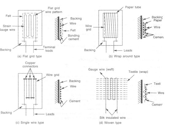
Wrap-Around Type This type of gauge is wound on a flattened tube of paper, or alternately, on a thin strip or card as shown in Fig. 5.4(b). Gauge lengths smaller than that of the flat-grid type can be achieved for the same resistance value, but the gauge exhibits greater surface thickness since the grid wire is in two planes, introducing different transfer characteristics from that of the flat type and resulting in larger hysteresis and creep.
Single-Wire Gauges Single-wire types were developed to eliminate the cross-sensitivity factor. In this device single wires are stretched across and laid as shown in Fig. 5.4(c). Instead of loops formed by the same wires, thick copper wires are welded at the ends, reducing the cross sensitivity considerably. These gauges are not very popular and are intended for large gauge lengths only.
Woven Type This method of fabrication, as- shown in Fig. 5.4(d), is employed in gauges intended for the measurement of large strains. A silk-insulated Eureka wire is wound as the weft on a rayon wrap to form a woven-type gauge, which is useful for tests on fabrics and leather. High-temperature gauges of this type are developed with a glass fibre weave but they are not popular for common engineering applications.
For good sensitivity and faithful transmission of strain to the gauge, it is essential that the gauge wire should have high resistivity and large surface area. Such a high resistance can be achieved only with a thin wire of long length. The gauge is usually fabricated with a constantan wire of 20 microns diameter, wound in a grid format with as many loops as possible, laid side by side. In spite of its small diameter, the wire can withstand tension and compression easily, mainly because of the fact that the surface area is very large compared to its cross-section. This large bonded area controls the movements of the wire almost perfectly with no buckling. The sensitivity of the bonded wire gauge under compression is lower than that at tension by I to 2% only. A large length to width ratio in the grid structure is also desirable, to keep the transverse sensitivity minimum.
Wire strain gauges of the bonded type are easy to manufacture in large numbers at relatively low cost. The normal gauge factor; value is between 2.0 and 2.2, and materials having a higher gauge factor are not normally recommended because of their poor temperature characteristics. For materials having higher gauge factors, the transverse sensitivity is also considerable, unless they are specially reduced during manufacture. The current-carrying capability is usually limited because of the low area of cross- section of the wire, the normal value being 10 to 20 mA. It may be noted that stress concentrations can occur at the terminal and wire joints, causing fatigue failures.
Unbonded Strain Gauges
An unbonded strain gauge device is basically a free filament-sensing element where strain is transferred to the resistance wire directly without any backing. In a typical device, a few number of loops of high tensile strength resistance wire of 25 micron diameter of such materials as platinum tungsten alloy is wound bet\,,:een insulated pins, one of them attached to a stationary frame and the other to amovable frame, so that the winding experiences an increase or decrease of stress for a given force input. The schematic diagram of a typical displacement transducer wherein the measuring forces are transmitted to the platform containing the unbonded wire ~tructure by means of a force rod is shown in Fig. 5.5. The main advantage of this device lies in its radial symmetry which assists in the cancellation of spurious signals from transverse forces. The other advantages are very low hysteresis and creep (since the wire backing and bonding are avoided, unlike in the case of bonded gauges), miniaturization of the transduc- ing element by integration of the force-summing unit and the force-sensing components, and adaptability for high-temperature environments due to the welded construction. The main applications are in dis- placement transducers, pressure transducers, and accelerometers.
Foil Gauges
The foil strain gauge is basically an extension of the wire gauge, differing in its constructional features and having certain advantages in actual measurement. In foil gauges, the required grid pattern is formed

Unbonded strain gauge
hence better thermal stability. a larger ratio of the bonding area to the cross-sectional area is achieved compared to the wire gauges. This in turn enables a higher heat dissipation and better bonding properties. The strain repro- ducibility is also excellent. By making the perpendicular sections of the foil wide, the response of the gauge to the traverse strain can be considerably reduced. In the foil type of gauges, there is no stress concentration at the terminals due to the absence of joints, thereby extending the life of the gauge. By virtue of the versatile photo-chemical etching process, any type of complex pattern of any small size can be fabricated easily, such as circular gauges, diaphragm gauges, orthogonal arrays for shear measurement and transducer applications as well as many types of Rosettes for two-dimensional stress analysis.
Semiconductor Strain Gauges
Semiconductor strain gauges employ the piezoresistive property of doped silicon and germanium. In the metal alloy strain gauges described earlier, the strain sensitivity is mainly due to the dimensional change with a lesser contribution due to the resistivity changes. Semiconductor strain gauges, developed as an offshoot of the integrated circuit technology, are fabricated from single crystals of silicon and germa- nium, where the strain sensitivity is mainly due to resistivity changes in the semiconductor material itself. A unique feature of the device is that the change in resistance due to strain is 40 to 100 times more than that of the conventional metal alloy types. In addition to the high gauge factor, other advantages are che- mical inertness, freedom from hysteresis and creep effects, good fatigue life, and low cross sensitivity.
Since the electrical resistivity varies with the degree of doping, the type of semiconductor material is usually conductivity and conduction mechanism. used for general purpose gauges is the p (iii)-type silicon doped with 2 x 10⁻⁴ ohm-m, at room temperature. The material is first groove-cut into slices, This is followed by cutting the pieces to thin filaments of about 150 microns thickness. The electrodes are funned by vapour deposition and ohmic electrical contacts are made with gold wires, attached by means of a thermocompression method. The strain gauges are then brought to their nominal resistance by electrolytic etching. For use as a strain gauge element, they are embedded on a film backing of phenolic. bakelite or epoxy.
The main characteristics specified fur a semiconductor gauge are: (a) Filament material-p- or n-type silicon (b) Gauge factor-positive or negative (c) Gauge length (d) Gauge resistance (e) Temperature coefficient (f) Backing or encapsulation (g) Bonding (cementing or welding) (h) Lead geometry .
Special solder material (cadmium-tin) is used for soldering the leads to the circuit. The semiconductor strain gauges are available with both positive and negative gauge factors, for p- and n-type silicon respectively. This enables to form bridge circuits with two active arms at one location itself, even when both the gauges are subjected to the same strain value. In the application of these gauges in transducers, the strain-sensitive diaphragm and other elements are fabricated as bonded gauges, or by diffusion techniques, as p-n junctions on silicon substrates. Some of the properties of these gauges are discussed below.
(a) Gauge Sensitivity The variation of gauge factors of p- and n-type silicon as a function of resistivity and crystal orientation, is illustrated in Fig. 5.8. The sensitivity of semiconductor gauges at low strain limits at room temperature is computed from the equation, Since the product 1t' is well in excess of 100, the contribution towards the sensitivity from the gauge geometry is insignificant when compared with the piezoresistive effect. Unlike wire gauges, a small The bonding techniques employed are similar to that for wire or foil gauges, except that greater care must be taken in
Bonded Strain Gage Transducers
A typical construction for a strain-gage load cell for measuring compressive forces is shown in Fig. (Cells to measure both tension and compression require merely the addition of suitable mechanical fittings at the ends). The load-sensing member is short enough to prevent column buckling under the rated load and is proportioned to develop about 1,500 µÎ at full-scale load (typical design value for al forms of foil gage transducers). Materials used include SAE 4340 steel, 17-4 pH stainless steel, and 2002-T4 aluminium alloy, with the last being quite popular for ‘homemade’ transducers. Foil-type metal gages are bonded on all four sides; gages 1 and 3 sense the direct stress due to Fi and gages 2 and 4 the transverse stress due to Poisson’s ratio µ. This arrangement gives a sensitivity 2(1+µ) times that achieved with a single active gage in the bridge. It also provides primary temperature compensation since all four gages (at least for steady temperatures) at the same temperature.
Strain Measurements
Let us first consider some basic definitions. Any strain measurement must be made over a finite length of the work piece. The smaller this length, the more nearly the measurement will approximate the unit strain at a point. The length over which the average strain measurement is taken is called the base length. The deformation sensitivity is defined as the minimum deformation that can be indicated by the appropriate gage. Strain sensitivity is the minimum deformation that can be indicated by the gage per unit base length.
A simple method of strain measurement is to place some type of grid marking on the surface of the work piece under zero-load conditions and then measure the deformation of this grid when the specimen is subjected to a load. The grid may be scribed on the surface, drawn with a fine ink pen, or photoetched. Rubber threads have also been used to mark the grid. The sensitivity of the grid method depends on the accuracy with which the displacement of the grid lines may be measured. A micrometer microscope is frequently employed for such measurements. An alternative method is to photograph the grid before and after the deformation and make the measurements on the developed photograph. Photographic paper can have appreciable shrinkage, so that glass photographic plates are preferred for such measurements. The grid may also be drawn on a rubber model of the specimen and the local strain for the model related to that which would be present in the actual work piece. Grid methods are usually applicable to materials and processes having appreciable deformation under load. These methods might be applicable to a study of the strains encountered in sheet-metal forming processes. The grid could be installed on a flat sheet of metal before it is formed. The deformation of the grid after forming gives the designer an indication of the local stresses induced in the material during the forming process.
Brittle coatings offer a convenient means for measuring the local stress in a material. The specimen or work piece is coated with a special substance having very brittle properties. When the specimen is subjected to a load, small cracks appear in the coating. These cracks appear when the state of tensile stress in the work piece reaches a certain value and thus may be taken as a direct indication of this local stress. The brittle coatings are valuable for obtaining an overall picture of the stress distribution over the surface of the specimen. They are particularly useful for determination of stresses at stress concentration points that are too small or inconveniently located for installation of electrical resistance or other types of strain gages. In some instances, stress data obtained from brittle – coating tests may be used to plan more precise strain measurements with resistance strain gages.
Tachogenerator
An electromechanical generator is a device capable of producing electrical power from mechanical energy, usually the turning of a shaft. When not connected to a load resistance, generators will generate voltage roughly proportional to shaft speed. With precise construction and design, generators can be built to produce very precise voltages for certain ranges of shaft speeds, thus making them well-suited as measurement devices for shaft speed in mechanical equipment. A generator specially designed and constructed for this use is called a tachometer or tachogenerator. Often, the word "tach" (pronounced "tack") is used rather than the whole word.
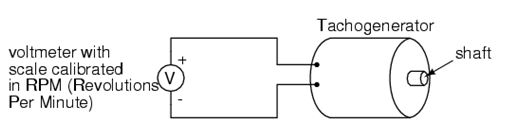
By measuring the voltage produced by a tachogenerator, you can easily determine the rotational speed of whatever its mechanically attached to. One of the more common voltage signal ranges used with tachogenerators is 0 to 10 volts. Obviously, since a tachogenerator cannot produce voltage when its not turning, the zero cannot be "live" in this signal standard. Tachogenerators can be purchased with different "full-scale" (10 volt) speeds for different applications. Although a voltage divider could theoretically be used with a tachogenerator to extend the measurable speed range in the 0-10 volt scale, it is not advisable to significantly overspeed a precision instrument like this, or its life will be shortened.
Tachogenerators can also indicate the direction of rotation by the polarity of the output voltage. When a permanent-magnet style DC generator's rotational direction is reversed, the polarity of its output voltage will switch. In measurement and control systems where directional indication is needed, tachogenerators provide an easy way to determine that.
Tachogenerators are frequently used to measure the speeds of electric motors, engines, and the equipment they power: conveyor belts, machine tools, mixers, fans, etc.
Last modified: Thursday, 5 December 2013, 9:24 AM