Site pages
Current course
Participants
General
Module 1. Average and effective value of sinusoida...
Module 2. Independent and dependent sources, loop ...
Module 3. Node voltage and node equations (Nodal v...
Module 4. Network theorems Thevenin’ s, Norton’ s,...
Module 5. Reciprocity and Maximum power transfer
Module 6. Star- Delta conversion solution of DC ci...
Module 7. Sinusoidal steady state response of circ...
Module 8. Instantaneous and average power, power f...
Module 9. Concept and analysis of balanced polypha...
Module 10. Laplace transform method of finding ste...
Module 11. Series and parallel resonance
Module 12. Classification of filters
Module 13. Constant-k, m-derived, terminating half...
LESSON 8. Network theorems:Superposition
8. Introduction to network theorems
Concept of a theorem: a relatively simple rule used to solve a problem, derived from a more intensive analysis using fundamental rules of mathematics. At least hypothetically, any problem in math can be solved just by using the simple rules of arithmetic (in fact, this is how modern digital computers carry out the most complex mathematical calculations: by repeating many cycles of additions and subtractions!), but human beings aren’t as consistent or as fast as a digital computer. We need “shortcut” methods in order to avoid procedural errors. In electric network analysis, the fundamental rules are Ohm’s Law and Kirchhoff ’s Laws. While these humble laws may be applied to analyze just about any circuit configuration (even if we have to resort to complex algebra to handle multiple unknowns), there are some “shortcut” methods of analysis to make the math easier for the average human. As with any theorem of geometry or algebra, these network theorems are derived from fundamental rules. In this chapter, I’m not going to delve into the formal proofs of any of these theorems. If you doubt their validity, you can always empirically test them by setting up example circuits and calculating values using the “old” (simultaneous equation) methods versus the “new” theorems, to see if the answers coincide. They always should!
8.1 Superposition Theorem
Superposition theorem is one of those strokes of genius that takes a complex subject and simplifies it in a way that makes perfect sense. A theorem like Millman’s certainly works well, but it is not quite obvious why it works so well. Superposition, on the other hand, is obvious. The strategy used in the Superposition Theorem is to eliminate all but one source of power within a network at a time, using series/parallel analysis to determine voltage drops (and/or currents) within the modified network for each power source separately. Then, once voltage drops and/or currents have been determined for each power source working separately, the values are all “superimposed” on top of each other (added algebraically) to find the actual voltage drops/currents with all sources active. Let’s look at our example circuit again and apply Superposition Theorem to it:
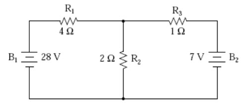
Fig.8.1
Since we have two sources of power in this circuit, we will have to calculate two sets of values for voltage drops and/or currents, one for the circuit with only the 28 volt battery in effect and one for the circuit with only the 7 volt battery in effect:

Fig. 8.2 Fig. 8.3
When re-drawing the circuit for series/parallel analysis with one source, all other voltage sources are replaced by wires (shorts), and all current sources with open circuits (breaks).Since we only have voltage sources (batteries) in our example circuit, we will replace every inactive source during analysis with a wire. Analyzing the circuit with only the 28 volt battery, we obtain the following values for voltage and current:
|
|
R1+R2// R3 |
|
||||
|
|
R1 |
R2 |
R3 |
R2// R3 |
Total |
|
|
E |
24 |
4 |
4 |
4 |
28 |
Volts |
|
I |
6 |
2 |
4 |
6 |
6 |
Amps |
|
R |
4 |
2 |
4 |
0.667 |
4.667 |
Ohms |
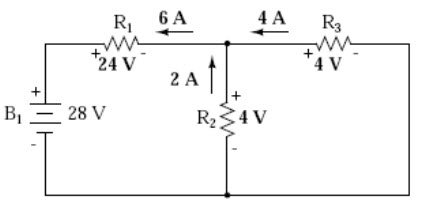 Fig. 8.4
Analyzing the circuit with only the 7 volt battery, we obtain another set of values for voltage and current:
|
|
R3+R1// R2 |
|
||||
|
|
R1 |
R2 |
R3 |
R1// R2 |
Total |
|
|
E |
4 |
4 |
3 |
4 |
7 |
Volts |
|
I |
1 |
2 |
3 |
3 |
3 |
Amps |
|
R |
4 |
2 |
1 |
1.333 |
2.333 |
Ohms |
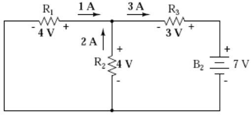
Fig. 8.5
When superimposing these values of voltage and current, we have to be very careful to consider polarity (voltage drop) and direction (electron flow), as the values have to be added algebraically.
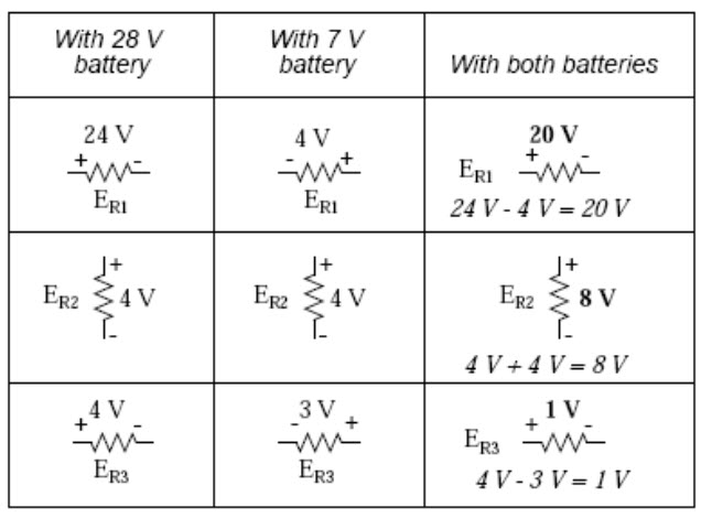
Fig. 8.6
Applying these superimposed voltage figures to the circuit, the end result looks something like this:
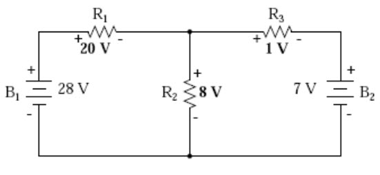
Fig. 8.7
Currents add up algebraically as well, and can either be superimposed as done with the resistor voltage drops, or simply calculated from the final voltage drops and respective resistances (I=E/R). Either way, the answers will be the same. Here I will show the superposition method applied to current:
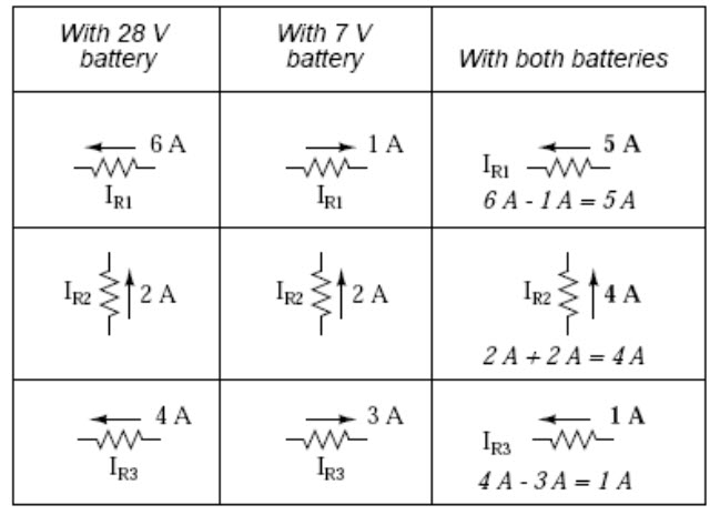
Fig. 8.8
Once again applying these superimposed figures to our circuit:
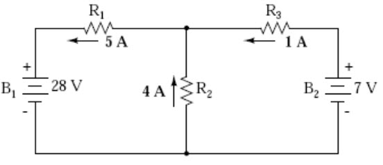
Fig. 8.9
Quite simple and elegant, don’t you think? It must be noted, though, that the Superposition Theorem works only for circuits that are reducible to series/parallel combinations for each of the power sources at a time (thus, this theorem is useless for analyzing an unbalanced bridge circuit), and it only works where the underlying equations are linear (no mathematical powers or roots). The requisite of linearity means that Superposition Theorem is only applicable for determining voltage and current, not power!!! Power dissipations, being nonlinear functions,
do not algebraically add to an accurate total when only one source is considered at a time. The need for linearity also means this Theorem cannot be applied in circuits where the resistance of a component changes with voltage or current. Hence, networks containing components like lamps (incandescent or gas-discharge) or varistors could not be analyzed. Another prerequisite for Superposition Theorem is that all components must be “bilateral,” meaning that they behave the same with electrons flowing either direction through them. Resistors have no polarity-specific behavior, and so the circuits we’ve been studying so far all meet this criterion. The Superposition Theorem finds use in the study of alternating current (AC) circuits, and semiconductor (amplifier) circuits, where sometimes AC is often mixed (superimposed) with DC. Because AC voltage and current equations (Ohm’s Law) are linear just like DC, we can use Superposition to analyze the circuit with just the DC power source, then just the AC power source, combining the results to tell what will happen with both AC and DC sources in effect. For now, though, Superposition will suffice as a break from having to do simultaneous equations to analyze a circuit.
REVIEW:
The Superposition Theorem states that a circuit can be analyzed with only one source of power at a time, the corresponding component voltages and currents algebraically added to find out what they’ll do with all power sources in effect.
To negate all but one power source for analysis, replace any source of voltage (batteries) with a wire; replace any current source with an open (break).