Site pages
Current course
Participants
General
Module 1. Average and effective value of sinusoida...
Module 2. Independent and dependent sources, loop ...
Module 3. Node voltage and node equations (Nodal v...
Module 4. Network theorems Thevenin’ s, Norton’ s,...
Module 5. Reciprocity and Maximum power transfer
Module 6. Star- Delta conversion solution of DC ci...
Module 7. Sinusoidal steady state response of circ...
Module 8. Instantaneous and average power, power f...
Module 9. Concept and analysis of balanced polypha...
Module 10. Laplace transform method of finding ste...
Module 11. Series and parallel resonance
Module 12. Classification of filters
Module 13. Constant-k, m-derived, terminating half...
LESSON 21. Voltage, Current and Power in a Star and Delta Connected System
21.1 Star-Connected System
Figure 21.1 shows a balanced three-phase, Y-connected system. The voltage induced in each winding is called the phase voltage (VPh). Likewise VRN’ VYN and VBN represent the rms values of the induced voltages in each phase. The voltage available between any pair of terminals is called the line voltage (V1). Likewise VRY’ VYB and VBR are known as line voltages. The double subscript notation is purposefully used to represent voltages and currents in polyphase circuits. Thus, VRY indicates a voltage V between points R and Y, with R being positive with respect to point Y during its positive half cycle.
Similarly, VYB means that Y is positive with respect to point B during its positive half cycle, it also means that VRY = -VYR’
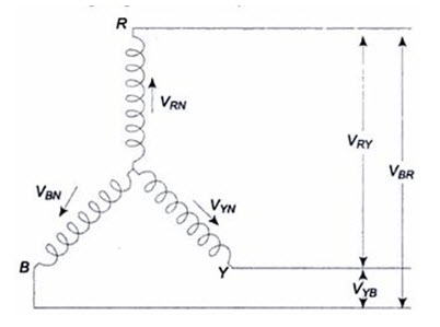
Fig .21.1
Voltage Relation
The phasors corresponding to the phase voltages constituting a three-phase system can be represented by a phasor diagram as shown in Fig.21.2.
From Fig.21.2, considering the lines R, Y and B, the line voltage VRY is equal to the phasor sum of VRN and VNY which is also equal to the phasor difference of VRN and VYN (VNT=-VYN). Hence, VRY is found by compounding VRN and VYN reserved.
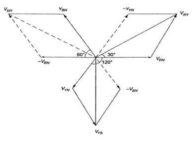
Fig.21.2
To subtract VYN from VRN’ we reverse the phasor VYN and find its phasor sum with VRN as shown in Fig.21.2. The two phasors, VRN and –VYN’ are equal in length and are 600 apart.
\[\left| {{V_{RN}}} \right|=-\left| {{V_Y}_N} \right|={V_{ph}}\]
\[{V_{RY}}=2{V_{ph}}\cos \,60/2=\sqrt 3 \,\,{V_{ph}}\]
Similarly, the line voltage VYB is equal to the phasor difference of VYN and VBN’ and is equal to \[\sqrt 3 \,{V_{ph}}.\] The line voltage VBR is equal to the phasor difference of VBN and VRN’ and is equal to \[\sqrt 3 \,{V_{ph}}.\] Hence, in a balanced star-connected system
(i) Line voltage = \[\sqrt 3 \,{V_{ph}}.\]
(ii) All line voltages are equal in magnitude and are displaced by 1200, and
(iii) All line voltages are 300 ahead of their respective phase voltages (from Fig.21.2).
Current Relations
Figure 21.3 (a) shows a balanced three-phase, wye-connected system indicating phase currents and line currents. The arrows placed alongside the currents IR’ IY and IB flowing in the three phases indicate the directions of currents when they are assumed to be positive and not the directions at that particular instant. The phasor diagram for phase currents with respect to their phase voltages is shown in Fig.21.3 (b). All the phase currents are displaced by 1200 with respect to each other, ‘ø’ is the phase angle between phase voltage and phase current (lagging load is assumed). For a balanced load, all the phase currents are equal in magnitude. It can be observed from Fig.21.3 (a) that each line conductor is connected in series with its individual phase winding. Therefore, the current in a line conductor is the same as that in the phase to which the line conductor is connected.
IL = Iph = IR = IY = IB
It can be observed from Fig. 21.3 (b) that the angle between the line (phase) current and the corresponding line voltage is (30 + ø)0 for a lagging load. Consequent, if the load is leading, then the angle between the line (phase) current and corresponding line voltage will be (30 - ø)0.
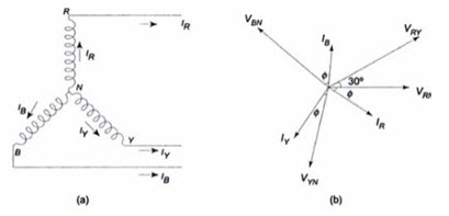
Fig.21.3
Power in the Star-Connected Network
The total active power or true power in the three-phase load is the sum of the powers in the three phases. For a balanced load, the power in each load is the same; hence total power = 3 x power in each phase
or P = 3 ´ Vph ´ Iph cos ø
It is the usual practice to express the three-phase power in terms of line quantities as follows.
\[{V_L}=\sqrt 3 \,\,{V_{ph'}}\,{I_L}={1_{ph}}\]
\[P=\sqrt 3 \,{V_L}{I_L}\,\cos \,\phi W\]
or \[\sqrt 3 {V_L}{I_L}\,\cos \,\phi\] is the active power in the circuit.
Total reactive power is given by
\[Q=\sqrt 3 {V_L}{I_L}\,\sin \,\phi \,VAR\]
Total apparent power or volt-amperes
\[=\sqrt 3 {V_L}{I_L}\,VA\]
n-phase Star System
It is to be noted that star and mesh are general terms applicable to any number of phases; but wye and delta are special cases of star and mesh when the system is a three-phase system. Consider an n-phase balanced star system with two adjacent phases as shown in Fig.21.4 (a). Its vector diagram is shown in Fig.21.4 (b).
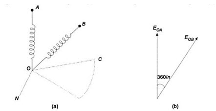
Fig. 21.4
The angle of phase differences between adjacent phase voltages is 3600 /n. Let Eph be the voltage of each phase. The line voltage, i.e. the voltage between A and B is equal to EAB = EL – EAO + EOB. The vector addition is shown in Fig.21.4 (c). It is evident that the line current and phase current are same.
EAB = EAO + EOB
Consider the parallelogram OABC.
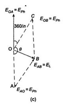
Fig.21.4 (c)
\[OB=\sqrt {O{C^2} + O{A^2} + 2 \times OA \times OC \times COS\theta }\]
\[=\,\sqrt {E_{ph}^2 + E_{ph}^2 + 2E_{ph}^2\,\cos \left( {{{180}^0} - {{{{360}^0}} \over n}} \right)}\]
\[=\,\sqrt {2E_{ph}^2\,\,2E_{ph}^2\,\cos {{{{360}^0}} \over n}}\]
\[=\sqrt 2 \,{E_{ph}}\sqrt {\left[ {1 - \cos 2\left( {{{{{180}^0}} \over n}} \right)} \right]}\]
\[=\sqrt 2 \,{E_{ph}}\sqrt {2{{\sin }^2}\left( {{{{{180}^0}} \over n}} \right)}\]
\[{E_L}=2{E_{ph}}\sin \,{{180} \over n}\]
The above equation is a general equation for line voltage, for example, for a three-phase system, n = 3; EL = 2 Eph sin 600 = \[\sqrt 3 {E_{ph}}.\]
21.2. Voltage, Current and Power in a Delta Connected System
Delta-Connected System
Figure 21.5 shows a balanced three-phase, three-wire, delta-connected system. This arrangement is referred to as mesh connection because it forms a closed circuit. It is also known as delta connection because the three branches in the circuit can also be arranged in the shape of delta (Δ).
From the manner of interconnection of the three phases in the circuit, it may appear that the three phase are short-circuited among themselves. However, this is not the case. Since the system is balanced, the sum of the three voltages round the closed mesh is zero; consequently, no current can flow around the mesh when the terminals are open.
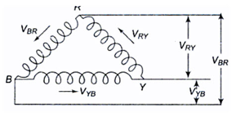
Fig.21.5
The arrows placed alongside the voltages, VRY’ VYB and VBR’ of the three phases indicate that the terminals R, Y and B are positive with respect to Y, B and R, respectively, during their respective positive half cycles.
Voltage Relation
From Fig.21.6, we notice that only one phase is connected between any two lines. Hence, the voltage between any two lines (V1) is equal to the phase voltage (Vph).
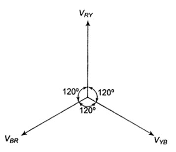
Fig.21.6
Since the system is balanced, all the phase voltages are equal, but displaced by 1200 from one another as shown in the phasor diagram in Fig.21.6. The phase sequence RYB is assumed.
\[\,\left| {{V_{RY}}} \right|=\left| {{V_{YB}}} \right|=\left| {{V_{BR}}} \right|={V_L}={V_{ph}}\]
Current Relation
In Fig.21.7 we notice that, since the system is balanced, the three phase currents (Iph), i.e. IR’ IY’ IB are equal in magnitude but displaced by 1200 from one another as shown in Fig.21.7(b). I1’ I2 and I3 are the line currents (IL) i.e. I1 is the line current in line 1 connected to the common point of R. Similarly, I2 and I3 are the line currents in lines 2 and 3, connected to common points Y and B, respectively. Though here all the line currents are directed outwards, at no instant will all the three line currents flow in the same direction, either outwards or inwards. Because the three line currents are displaced 1200 from one another, when one is positive, the other two might both be negative, or one positive and one negative. Also it is to be noted that arrows placed alongside phase currents in Fig.21.7 (a), indicate the direction of currents when they are assumed to be positive and not their actual direction at a particular instant. We can easily determine the line currents in Fig. 21.7 (a), I1,I2 and I2 by applying KCL at the three terminals R, Y and B, respectively. Thus, the current in line 1, I1 = IR – IB; i.e. the current in any line is equal to the phasor difference of the currents in the two phases attached to that line. Similarly, the current in line 2, I2 = IY – IR’ and the current in line 3, I3 = IB -IY.
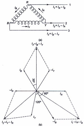 Fig. 21.7
The phasor addition of these currents is shown in Fig.21.7 (b). from the figure,
I1 = IR – IB
\[{I_1}=\sqrt {I_R^2 + I_B^2 + 2{I_R}{I_B}\,\,\cos \,{{60}^0}}\]
\[{I_1}=\sqrt {3\,} {I_{ph'}}\,\,\sin ce\,{I_R}={I_B}={I_{ph}}\]
Similarly, the remaining two line currents, I2 and I3’ are also equal to \[\sqrt 3\] times the phase currents; i.e. \[=\sqrt 3 \,\,{I_{ph}}\]
As can be seen from Fig.21.7 (b), all the line currents are equal in magnitude but displaced by 1200 from one another; and the line currents are 300 behind the respective phase currents.
Power in the Delta-Connected System
Obviously the total power in the delta circuit is the sum of the powers in the three phases. Since the load is balanced, the power consumed in each phase is the same. Total power is equal to three times the power in each phase.
Power per phase = Vph Iph cos ø
Where ø is the phase angle between phase voltage and phase current.
Total power P = 3 ´ Vph Iph cos ø
In terms of line quantities
\[P=\sqrt 3 {V_L}{I_L}\,\cos \,\phi \,\,W\]
Since \[{V_{ph}}={V_L}\,\,and\,\,{I_{ph}}={{{I_L}} \over {\sqrt 3 }}\]
For a balanced system, whether star or delta, the expression for the total power is the same.
n-Phase Mesh System
Figure 21.8 (a) shows part of an n-phase balanced mesh system. Its vector diagram is shown in Fig.21.8 (b).
Let the current in line BB’ be IL. This is same in all the remaining lines of the n-phase system. IAB’ IBC are the phase currents in AB and BC phases respectively. The vector addition of the line current is shown in Fig.21.8(c). It is evident from the Fig.21.8 (b) that the line and phase voltages are equal.
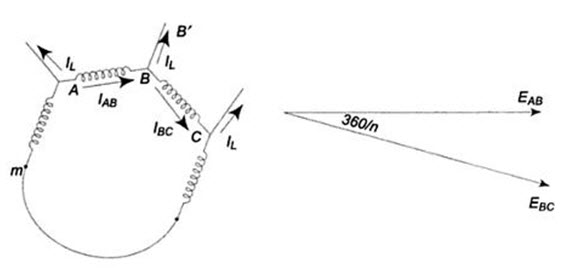
Fig.21.8 (a) Fig.21.8 (b)
IBB = IL = IAB + ICB
= IAB – IBC
Consider the parallelogram OABC.
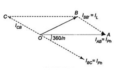
Fig.21.8 (c)
\[OB=\sqrt {O{A^2} + O{C^2} + 2 \times OA \times OC \times \cos \left( {180 - {{360} \over n}} \right)}\]
\[=\sqrt {I_{ph}^2\,\,I_{ph}^2\,\,2I_{ph}^2\,\,\cos \,\,{{360} \over n}}\]
\[=\sqrt 2 \,\,{I_{ph}}\sqrt {1\,\,\,\cos 2\left( {{{180} \over n}} \right)}\]
\[=\sqrt 2 \,\,{I_{ph}}\sqrt {2\,\,\,{{\cos }^2}\left( {{{180} \over n}} \right)}\]
\[{I_L}\,=2{I_{ph\,}}\,\sin \,{{180} \over n}\]
The above equation is a general equation for the line current in a balanced n-phase mesh system.
Last modified: Thursday, 26 September 2013, 11:20 AM