Site pages
Current course
Participants
General
Module 1. Average and effective value of sinusoida...
Module 2. Independent and dependent sources, loop ...
Module 3. Node voltage and node equations (Nodal v...
Module 4. Network theorems Thevenin’ s, Norton’ s,...
Module 5. Reciprocity and Maximum power transfer
Module 6. Star- Delta conversion solution of DC ci...
Module 7. Sinusoidal steady state response of circ...
Module 8. Instantaneous and average power, power f...
Module 9. Concept and analysis of balanced polypha...
Module 10. Laplace transform method of finding ste...
Module 11. Series and parallel resonance
Module 12. Classification of filters
Module 13. Constant-k, m-derived, terminating half...
LESSON 22. Three-Phase Balanced Circuits
22.1. Three-Phase Balanced Circuits
The analysis of three-phase balanced system is presented in this section. It is no way different from the analysis of AC systems in general. The relation between voltages, currents and power in delta-connected and star-connected systems has already been discussed in the previous sections. We can make use of those relations and expressions while solving the circuits.
Balanced Three-Phase System-Delta Load
Figure 22.1 (a) shows a three-phase, three-wire, balanced system supplying power to a balanced three-phase delta load. The phase sequence is RYB. We are required to find out the currents in all branches and lines.
Let us assume the line voltage VRY=V \[\angle\] 00 as the reference phasor. Then the three source voltages are given by
VRY=V\[\angle\]00 V
VYB=V\[\angle\]=1200 V
VBR=V\[\angle\]2400 V
These voltages are represented by phasors in Fig.22.1 (b). Since the load is delta-connected, the line voltage of the source is equal to the phase voltage of the load. The current in phase RY, IR will lag (lead) behind (ahead of) the phase voltage VRY by an angle f as dictated by the nature of the load impedance. The angle of lag of Ir with respect to VYB’ as well as the angle of lag of IB with respect to VBR will be f as the load is balanced. All these quantities are represented in Fig. 22.1 (b).
If the load impedance is Z \[\angle\]ø, the current flowing in the three load impedances are then
\[{I_R}={{V_{RY}^{} - 0} \over {Z - \varphi }}={V \over Z}\angle-\varphi\]
\[{I_Y}={{V_{YB}^{} - 120} \over {Z - \phi }}={V \over Z}\angle-{120^0}-\phi\]
\[{I_B}={{V_{BR}^{} - 120} \over {Z - \phi }}={V \over Z}\angle-{120^0}-\phi\]
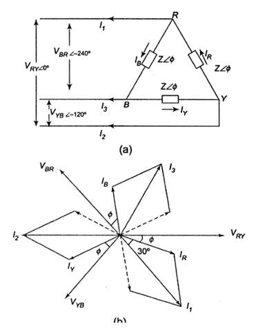
Fig.22.1
The line currents are \[\sqrt 3\] times the phase currents, and are 300 behind their respective phase currents.
Current in line 1 is given by
\[{I_1}=\sqrt 3 \left| {{V \over Z}} \right|\,\angle \left( {-\phi-{{30}^0}} \right),\,\,or\,\,{I_R} - {I_B}\,\,\left( {phasor\,\,difference} \right)\]
Similarly, the current in line 2
\[{I_2}=\sqrt 3 \left| {{V \over Z}} \right|\,\angle \left({-120-\varphi-{{30}^0}} \right),\,\,\]
or \[{I_Y} - {I_R}\,\,\left({phasor\,\,difference}\right)\,\,\, = \,\,\sqrt 3\left| {{V \over Z}} \right|\,\,\angle \left({-\phi-{{150}^0}}\right),\,\,and\]
\[{I_3}=\sqrt 3 \left| {{V \over Z}} \right|\,\angle \left({-120-\phi-{{30}^0}} \right),\,\,or\,\,{I_B} - {I_Y}\,\,\left({phasor\,\,difference} \right)\,\,\]
\[=\sqrt 3 \left| {{V \over Z}} \right|\, - \left( {120-\phi}\right)\]
To draw all these quantities vectorially, VRY=V\[\angle\]00 is taken as the reference vector.
Balanced Three Phase System-Star Connected Load
Figure 22.2(a) shows a three-phase, three wire system supplying power to a balanced three phase star connected load. The phase sequence RYB is assumed.
In star connection, whatever current is flowing in the phase is also flowing in the line. The three line (phase) currents are IR’ IY and IB.
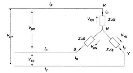
Fig.22.2(a)
VRN’ VYN and VBN represent three phase voltage of the network, i.e. the voltage between any line and neutral. Let us assume the voltage VRN = V\[\angle\]00 as the reference phasor. Consequently, the phase voltage.
\[{V_{RN}}\,=\,V\,\angle {0^0}\]
\[{V_{YN}}\,=\,V\,\angle-{120^0}\]
\[{V_{BN}}\,=\,V\,\angle-{240^0}\]
Hence \[{I_R}={{{V_{RN}}} \over {Z\angle \phi }}={{V - 0} \over {Z - \phi }}=\left| {{V \over Z}} \right|\angle-\phi\]
\[{I_Y}={{{V_{YN}}}\over {Z - \phi }}={{V - 120} \over {Z - \phi }}=\left| {{V \over Z}} \right|\angle-{120^0}-\phi\]
\[{I_B}={{{V_{BN}}} \over {Z - \phi }}={{V - 240} \over {Z - \phi }}=\left| {{V \over Z}} \right|\angle-{240^0}-\phi\]
As seen from the above expressions, the currents, IR’ IY and IB’ are equal in magnitude and have a 1200 phase difference. The disposition of these vectors is shown in Fig.22.2(b). Sometimes, a 4th wire, called neutral wire is run from the neutral point, if the source is also star-connected. This given three-phase, four-wire star-connected system. however, if the three line currents are balanced, the current in the fourth wire is zero; removing this connecting wire between the source neutral and load neutral is, therefore, not going to make any change in the condition of the system. the availability of the neutral wire makes it possible to use all the three phase voltages, as well as the three line voltages. Usually, the neutral is grounded for safety and for the design of insulation.
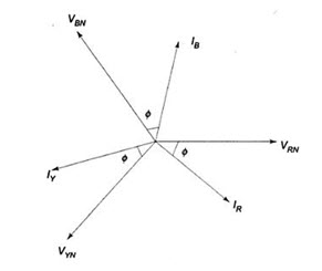
Fig. 22.2 (b)
It makes no different to the current flowing in the load phases, as well as to the line currents, whether the sources have been connected in star or in delta, provided the voltage across each phase of the delta connected source is \[\sqrt 3\] times the voltage across each phase of the star-connected source.
22.10. Three-Phase-Unbalanced Circuits
Types of Unbalanced Loads
An unbalance exists in a circuit when the impedances in one or more phases differ from the impedances of the other phases. In such a case, line or phase currents are different and are displaced from one another by unequal angles. So far, we have considered balanced loads connected to balanced systems. It is enough to solve problems, considering one phase only on balanced loads, the conditions on other two phases being similar. Problems on unbalanced three-phase loads are difficult to handle because conditions in the three phases are different. However, the source voltages are assumed to be balanced. If the system is a three-wire system, the currents flowing towards the load in the three liens must add to zero at any given instant. If the system is a four-wire system, the sum of the three outgoing line currents is equal to the return current in the neutral wire. We will now consider different methods to handle unbalanced star-connected and delta-connected loads. In practice, we may come across the following unbalanced loads:
(i) Unbalanced delta-connected load
(ii) Unbalanced three-wire star-connected load, and
(iii) Unbalanced four-wire star-connected load.
Unbalanced Delta-connected Load
Figure 22.3 shows an unbalanced delta-load connected to a balanced three-phase supply.
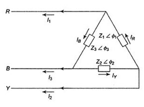
Fig. 22.3
The unbalanced delta-connected load supplied from a balanced three-phase supply does not present any new problems because the voltage across the load phase is fixed. It is independent of the nature of the load and is equal to the line voltage of the supply. The current in each load phase is equal to the line voltage divided by the impedance of that phase. The line current will be the phasor difference of the corresponding phase currents, taking VRY as the reference phasor.
Assuming RYB phase sequence, we have
\[{V_{RY}}=V\,\angle {0^0}\,\,V,\,\,{V_{YB}}=V\,\,\angle-{120_0}\,V,\,\,{V_{BR}}\,=\,\,V\,\,\angle \, - {240^0}\,\,V\]
Phase currents are
\[{I_R}={{{V_{RY}}} \over {{Z_1}\angle \phi }}={{V\angle {0^0}} \over {{Z_1}\angle {\phi _1}}}=\left| {{V \over {{Z_1}}}} \right|\,\angle {\phi _1}\,A\]
\[{I_Y}={{{V_{YB}}} \over {{Z_2}\angle {\phi _2}}}={{V\angle-{{120}^0}} \over {{Z_2}\angle {\phi _2}}}=\left| {{V \over {{Z_2}}}} \right|\,\angle- {120^0} - {\phi _2}\,A\]
\[{I_B}={{{V_{BR}}} \over {{Z_3}\angle {\phi _3}}}={{V\angle-{{120}^0}} \over {{Z_3}\angle {\phi _3}}}=\left| {{V \over {{Z_3}}}} \right|\,\angle- {120^0} - {\phi _3}\,A\]
The three line currents are
I1 = IR-IB phasor difference
I2 = IY-IR phasor difference
I3 = IB-IY phasor difference
Unbalanced Four Wire-Connected Load
Figure 22.4 shows an unbalanced star load connected to a balanced 3-phase, 4-wire supply.
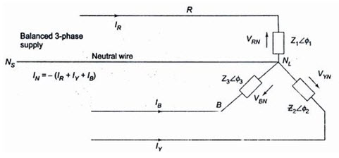
Fig. 22.4
The star point, NL’ of the load is connected to the star point, NS of the supply. It is the simplest case of an unbalanced load because of the presence of the neutral wire; the star points of the supply NS (generator) and the load NL are at the same potential. It means that the voltage across each load impedance is equal to the phase voltage of the supply (generator), i.e. the voltage across the three load impedances are equalized even though load impedances are unequal. However, the current in each phase (or line) will be different. Obviously, the vector sum of the currents in the three lines is not zero, but is equal to neutral current. Phase currents can be calculated in similar way as that followed in an unbalanced delta-connected load.
Taking the phase voltage \[VRN=V\angle {0^{0}}V\] as reference, and assuming RYB phase sequences; we have the three phase voltages as follows.
\[VRN=V\angle {0^{0}}V,{V_{YN}}=V\angle-{120^{0}}V,{V_{BN}}=V\angle-{240^{0}}\]
The phase currents are
\[{I_R}={{{V_{RN}}} \over {{Z_1}}}={{V\,\angle {0^0}} \over {{Z_1}\angle {\phi _1}}}A=\left| {{V \over {{Z_1}}}} \right|\angle-{\phi _1}A\]
\[{I_Y}={{{V_{YN}}} \over {{Z_2}}}={{V\,\angle {{120}^0}} \over {{Z_1}\angle{\phi _2}}}A=\left|{{V\over{{Z_2}}}}\right|\angle-{120^0}-{\phi _2}A\]
\[{I_B}={{{V_{BN}}} \over {{Z_3}}}={{V\,\angle {{120}^0}} \over {{Z_3}\angle{\phi _3}}}A=\left|{{V\over {{Z_3}}}}\right|\angle-{240^0}-{\phi _3}A\]
Incidentally, IR’ IY and IB are also the line currents; the current in the neutral wire is the vector sum of the three line currents.
Unbalanced Three Wire Star-Connected Load
In a three-phase, four-wire system if the connection between supply neutral and load neutral is broken, it would result in an unbalanced three-wire star-load. This type of load is rarely found in practice, because all the three wire star loads are balanced. Such as system is shown in Fig.22.5. Note that the supply star point (NS) is isolated from the load star point (NL). The potential of the load star pint is different from that of the supply star point. The result is that the load phase voltages are not equal to the supply phase voltage; and they are not only unequal in magnitude, but also subtend angles other than 1200 with one another. The magnitude of each phase voltage depends upon the individual phase loads. The potential of the load neutral point changes according to changes in the impedances of the phases that is why sometimes the load neutral is also called a floating neutral point. All-star-connected, unbalanced loads supplied from polyphase systems without a neutral wire have floating neutral point. The phasor sum of the three unbalanced line currents is zero. The phase voltage of the load is not \[1\sqrt 3\] of the line voltage. The unbalanced three-wire star load is difficult to deal with. It is because load phase voltages cannot be determined directly from the given supply line voltages. There are many methods to solve such unbalanced Y-connected loads. Two frequently used methods are presented here. They are
(i) Star-delta conversion method, and
(ii) The application of Millman’s theorem
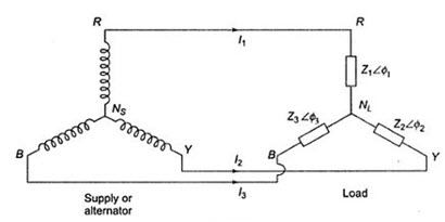
Fig. 22.5
Last modified: Friday, 27 September 2013, 4:28 AM