Site pages
Current course
Participants
General
Module- 1 Scope and importance of food processing....
Module- 2 Processing of farm crops; cereals, pulse...
Module- 3 Processing of animal products
Module- 4 Principal of size reduction, grain shape...
Module- 5 Theory of mixing, types of mixtures for ...
Module- 6 Theory of separation, size and un sized ...
Module- 7 Theory of filtration, study of different...
Module- 8 Scope & importance of material handl...
19 April - 25 April
26 April - 2 May
Lesson 18. Types of mixtures for dry and paste materials
18.0 Introduction
In general terms, mixers for dry solids have nothing to do with mixers involving a liquid phase, as solid particles are subjected to various interactive forces which are not self-diffusive. Powders cannot be set in motion without an external force such as mechanical agitation According to the mixing mechanisms previously discussed solids mixers can be classified into two groups: segregating mixers and non-segregating mixers. The former operate mainly by a diffusive mechanism, while the latter practically involve a convective mechanism. Segregating mixers are normally non-impeller type units, such as tumbling mixers, whereas non-segregating mixers may include screws, blades, and ploughs in their designs; examples of them include horizontal trough mixers and vertical screw mixers. Furthermore, mixing can operate in batch or continuous modes. The following sections will describe batch type blenders in detail and will mention some aspects of continuous blending.
18.1 Tumbler Mixers
Free-flowing non-segregating powders may be readily mixed in batch by use of tumbler mixers. Tumbler mixers operate by tumbling the mass of solids inside a revolving vessel. Blenders are available in various geometries, affecting material movement, mixing efficiency and ease of cleaning between batches. These vessels take various forms, such as those illustrated in Fig. 17.1, and may be fitted with baffles or stays to improve their performance. A tumbling batch blender can be of four types, which are described as follows:
(a) Horizontal cylinder (Fig. 17.1a): This cylindrical mixer has a tubular vessel mounted on trunnions. Internal baffles or lifter bars are mounted along the inner walls of the vessel. The inlet is typically located at the top center of the vessel and the outlet at the bottom center. The blender tumbles and the internal baffles gently lift and aerate the material preventing it from sliding along the blender bottom; they also de-lump the material.
(b) Double cone blender (Fig. 17.1b): The double cone blender consists of two cone-shaped sections, typically with 45o slopes. The cone sections are welded at their ends to a center band. The blender is mounted between two trunnions that permit the unit to tumble end over end. An opening in one of the ends of the cones serves as inlet and outlet, or the inlet can be in one cone end with the outlet in the other. Cleaning access is through the outlet. The blender tumbles, and the material in the vessel spreads out. The transition area at the band between the cones prevents the material from sliding along the inner wall and instead causes the material to fold over itself. This provides gentle mixing with only very slight shear.
(c) V-cone blender (Fig.17.1c) and Y-cone blender (Fig. 17.1d): The V-cone blender is similar to a double cone unit, but consists of two large diameter pipe sections cut at a 45◦-angle and welded together to form a V. In the same way, the Y-cone blender has a third section that extends the volume of the blender in a bisectional direction with respect to the other pipe sections. Inlets are typically located at both ends of the V (or of the Y); the outlet is at the V point (or at the bottom of the Y). The unit is also mounted on trunnions to allow it to tumble and can be equipped with a spray line for liquid addition and an agitator for de-lumping. The units tumble end over end as in the double cone blender. The free-falling action combined with increased frictional contact between the material and the long vessel sides result in less gentle mixing than in a double cone blender.
From the outlets of the mixers, the batch can be discharged via an optional retractable sleeve into drums or containers for shipping. The mixer’s tumbling action distributes the materials along an ever changing angle of repose surface. Tumbler mixers can be used to provide a gentle mixing required to avoid attrition of friable materials. The shells rotate at variable speeds having values up to 100 rev/min with working capacities around 50–60% of the total vessel volume. Rotational speed is set at 50–80% of the critical rotational speed, Ncr, given as:
\[N_{cr}={{0.498} \over {\sqrt {R_{\max } } }}(s^{ - 1} )\]...........................................................(17.1)
where Rmax (m) is the maximum radius of rotation of the mixer. The rate of mixing is rather low, but a good final degree of mixedness can be expected.
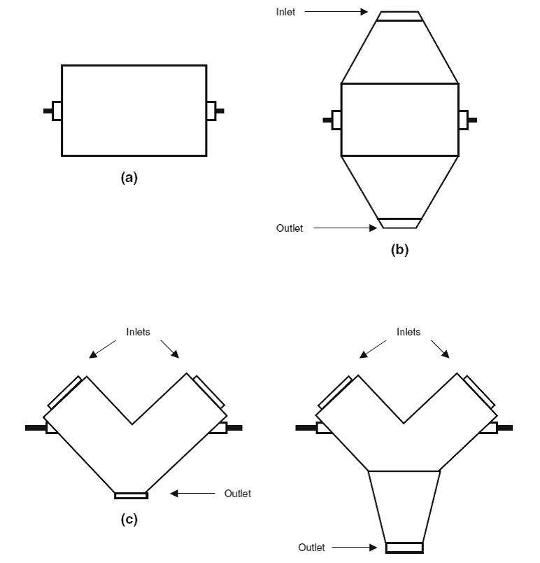
Fig. 18.1 Tumbler mixers used in food powder blending: (a) horizontal cylinder; (b) double cone; (c) V-cone; and (d) Y-cone.
Tumbler mixers are manufactured using a wide variety of materials, including stainless steel. Batch ingredients can be weighed automatically as they enter the mixing vessel rather than individually prior to mixing. Once the desired weight has been reached, rotation start can be automatically controlled by computerized systems. This type of mixer can create a free falling curtain of material, exposing each particle surface area and allowing uniform dispersion of liquid additives. Liquid addition can include for coating and encapsulating applications. This type of equipment is best suited for gentle blending of powders with similar physical characteristics. Segregation can represent a problem if particles vary, particularly in size and shape. Thus, careful design is required to minimize degree of segregation.
One of the main disadvantages of this type of blender is the demixing possibility due to the funnel flow pattern formation that can occur upon discharging. Very few double cone or V-cone blenders have hopper surfaces steep enough and sufficiently low in friction to provide mass-flow discharge. One possible solution would be to connect the tumble blending unit to a mass flow container. In fact, a special device called the cone-in-cone bin has tumbling and mass flow discharge possibilities, thereby eliminating segregation upon discharge, while maximizing the capacity of the container.
18.2 Horizontal and Vertical Trough Mixers
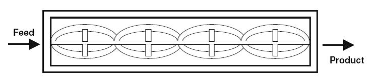
Horizontal trough mixers consist of a semi-cylindrical horizontal vessel in which one or more rotating devices are located. For simple operations, single or twin screw conveyors are appropriate and one passage through such a system may be good enough. For more demanding duties, a ribbon mixer, like the one shown in Fig. 17.2, may be used. A typical design of a ribbon mixer will consist of two counteracting helical blades (called ribbons or spirals) mounted on the same shaft. Ribbons convey materials inside and outside in opposite directions forcing them to intermix. The mixing tool and vessel are typically made of stainless steel. One moves the solids slowly in one direction, while the other moves it quickly in the opposite direction. There is a resultant movement of solids in one direction, so the equipment can be used as a continuous mixer. Some other types of ribbon mixers operate on a batch basis. The mixer can have more than one discharge so different batches can be discharged to different processing lines. In these designs, troughs may be closed to minimize dust hazard, or may be jacketed to allow temperature control. Due to small clearance between the ribbon and the trough wall, this kind of mixer can cause particle damage and may consume high amounts of power. Another possibility is that the ribbon mixer is in its vertical position. These mixers operate at relatively low speed to gently handle materials while providing enough intensity to thoroughly blend them in a relatively short time cycle (typically 1/3 to 1/2 the time of conventional horizontal ribbon mixers). The mixer has a filling capacity of up to 90% of the gross volume of the mixer, thus improving process efficiency.
The vertical ribbon mixer is available in two types: single and double shaft. The single-shaft mixer (Fig. 17.3a) has a rotating shaft fitted with horizontal arms that support the ribbons. The shaft, arms, and blades together are the mixing tool. The rotating shaft runs through the center of a cylindrical, vertically oriented air- and watertight vessel. Once the ingredients are in the vessel, the rotation creates an upward screw-like movement of the ingredients along the vessel periphery and a downward movement along the shaft through the vessel center. The double-shaft mixer (Fig. 17.4b) functions similarly to the single shaft unit. However, both shafts rotate in the same direction at somewhat higher speed, creating a synchronized crosswise mixing pattern.
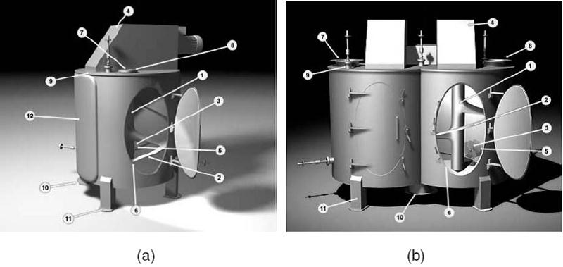
fig_17.3 (a) vertical singal mixer and (b) vertical double-shaft mixer
(1) filling ratios 10–100%; (2) adjustable distance between base and mixing apparatus; (3) cutting rotors; (4) mixing tool motor; (5) liquid spray; (6) oval inspection door; (7) level indicator; (8) chemical aseptic flanges in connection pieces; (9) orbital tank washing heads; (10) discharge flap; (11) optional load cell mounting; (12) double jacket (courtesy of Amixon GmbH).
18.3 Vertical Screw Mixers
In vertical screw mixers, a rotating vertical screw is located in a cylindrical or cone shaped vessel. The screw may be mounted centrally in the vessel or may rotate or orbit around the central axis of the vessel near the wall. Materials are lifted from the bottom to the top of the hopper and are then exchanged with materials on the way up. Such mixers are schematically shown in Fig. 17.4. A vertical screw blender (Fig. 17.4a) may be desired for larger batches handled in a small space, while the orbiting screw mixer (Fig. 17.4b) is used for difficult mixes. The latter arrangement is more effective and stagnant layers near the wall are eliminated. Vertical screw mixers are quick, efficient, and particularly useful for mixing small quantities of additives into large masses of material. Specialized atmospheres as well as normal temperatures and pressures are accessible for multipurpose operations.
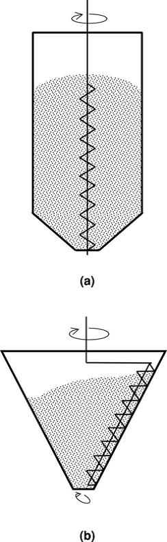
Fig.18.3 Vertical screw mixers: (a) central screw; and (b) orbiting screw.
18.4 Fluidized Bed Mixers
Food powders can also be mixed by aeration using a fluidized bed. The resulting turbulence of passing air through a bed of particulate material causes material to blend. Materials are moved upward by air jets, causing differential movement. Stationary vessels using gas-flow agitation are used primarily for batch mode mixing. Materials to be mixed have to be relatively fine and fairly narrow in their size distribution, as well as not too cohesive. Powders to be mixed can be charged to more than 70% of the vessel volume. Mixing times required in fluidized beds are significantly lower than those required in conventional powder mixers. The mixing is largely convective with the circulation patterns set up by the bubble motion within the bed. An important feature of the fluidized bed mixer is that several processing steps (mixing reaction, coating, drying, etc. may be carried out in the same vessel. Additional equipment can include blowers, dust collectors, and pressure regulators, which will enlarge the system as a whole. A particular type of the fluidized mixer is the fluidized paddle mixer (also called fluidized zone mixer). The mixer has twin troughs, each with a center mounted rotating shaft. Flat paddles are welded to spokes on each shaft. The paddles lift the material from the bottom and throw it into a zero gravity, fluidized mixing zone, settling a random displacement pattern for the material.
Last modified: Saturday, 5 October 2013, 10:24 AM