Site pages
Current course
Participants
General
Module 1. Average and effective value of sinusoida...
Module 2. Independent and dependent sources, loop ...
Module 3. Node voltage and node equations (Nodal v...
Module 4. Network theorems Thevenin’ s, Norton’ s,...
Module 5. Reciprocity and Maximum power transfer
Module 6. Star- Delta conversion solution of DC ci...
Module 7. Sinusoidal steady state response of circ...
Module 8. Instantaneous and average power, power f...
Module 9. Concept and analysis of balanced polypha...
Module 10. Laplace transform method of finding ste...
Module 11. Series and parallel resonance
Module 12. Classification of filters
Module 13. Constant-k, m-derived, terminating half...
LESSON 27. Parallel Resonance
27.1. Parallel Resonance
Basically, parallel resonance occurs when XC=XL. The frequency at which resonance occurs is called the resonant frequency. When XC=XL, the two branch currents are equal in magnitude and 1800 out of phase with each other. Therefore, the two currents cancel each other out, and the total current is zero. Consider the circuit shown in Fig.26.1. The condition for resonance occurs when XL=XC.
In fig. 26.1, the total admittance
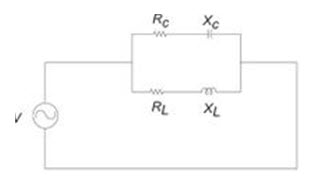
Fig. 27.1
\[Y={1 \over {{R_L} + j\omega L}} + {1 \over {{R_C} - \left( {j/\omega C} \right)}}\]
At resonance the susceptance part becomes zero
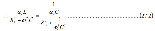
\[{\omega _r}L\left[ {R_C^2 + {1 \over {\omega _r^2{C^2}}}} \right]={1 \over {{\omega _r}C}}\left[ {R_L^2 + \omega _r^2{L^2}} \right]\]
\[\omega _r^2\left[ {R_C^2 + {1 \over {\omega _r^2{C^2}}}} \right] = {1 \over {LC}}\left[ {R_L^2 + \omega _r^2{L^2}} \right]\]
\[\omega _r^2R_C^2 - {{\omega _r^2} \over C}={1 \over {LC}}R_L^2 - {1 \over {{C^2}}}\]
\[\omega _r^2\left[ {R_C^2 - {L \over C}} \right]={1 \over {LC}}\left[ {R_L^2 - {L \over C}} \right]\]
\[{\omega _r}={1 \over {\sqrt {LC} }}\sqrt {{{R_L^2 - \left( {L/C} \right)} \over {R_C^2 - \left( {L/C} \right)}}} ...................................................\left( {27.3} \right)\]
The condition for resonant frequency is given by EQ.8.16. As a special case, if RL = RC, then Eq.27.3 becomes
\[{\omega _r}={1 \over {\sqrt {LC} }}\]
Therefore \[{f_r}={1 \over {2\pi \sqrt {LC} }}\]
27.2. Resonant Frequency for a Tank Circuit
The parallel resonant circuit is generally called a tank circuit because of the fact that the circuit stores energy in the magnetic field of the coil and in the electric field of the capacitor. The stored energy is transferred back and forth between the capacitor and coil and vice-versa. The tank circuit is shown in Fig.27.2. The circuit is said to be in resonant condition when the susceptance part of admittance is zero.
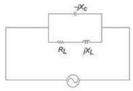
Fig.27.2
The total admittance is
\[Y={1 \over {{R_L} + j{X_L}}} + {1 \over { - j{X_C}}}...................................................\left( {27.4} \right)\]
Simplifying Eq. 27.4, we have
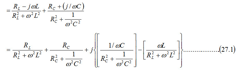
\[Y={{{R_L} - j{X_L}} \over {R_L^2 + X_L^2}} + {j \over {{X_C}}}\]
\[={{{R_L}} \over {R_L^2 + X_L^2}} + j\left[ {{1 \over {{X_C}}} - {{{X_L}} \over {R_L^2 + X_L^2}}} \right]\]
To satisfy the condition for resonance, the susceptance part is zero.
\[{1 \over {{X_C}}}={{{X_L}} \over {R_L^2 + X_L^2}}...................................................\left( {27.5} \right)\]
\[\omega C={{\omega L} \over {R_L^2 + {\omega ^2}{L^2}}}...................................................\left( {27.6} \right)\]
From Eq.27.6, we get
\[R_L^2 + {\omega ^2}{L^2}={L \over C}\]
\[{\omega ^2}{L^2}={L \over C} - R_L^2\]
\[{\omega ^2}={1 \over {LC}} - {{R_L^2} \over {{L^2}}}\]
\[\,\omega=\sqrt {{1 \over {LC}} - {{R_L^2} \over {{L^2}}}} ...................................................\left( {27.7} \right)\]
The resonant frequency for the tank circuit is
\[{f_r}={1 \over {2\pi }}\sqrt {{1 \over {LC}} - {{R_L^2} \over {{L^2}}}} ...................................................\left( {27.8} \right)\]
27.3. Variation of Impedance with Frequency
The impedance of a parallel resonant circuit is maximum at the resonant frequency and decreases at lower and higher frequencies as shown in Fig. 27.3.
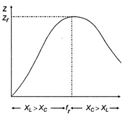
Fig.27.3
At very low frequencies, XL is very small and XC is very large, so the total impedance is essentially inductive. As the frequency increases, the impedance also increases, and the inductive reactance dominates until the resonant frequency is reached. At this point XL=XC and the impedance is at its maximum. As the frequency goes above resonance, capacitive reactance dominates and the impedance decreases.
27.4. Q Factor of Parallel Resonance
Consider the parallel RLC circuit shown in Fig. 27.4.
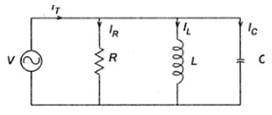
Fig.27.4
In the circuit shown, the condition for resonance occurs when the susceptance part is zero.
Admittance Y = G + jB \[...................................................\left( {27.9} \right)\]
\[={1 \over R} + j\omega C + {1 \over {j\omega L}}\]
\[={1 \over R} + j\left( {\omega C + {1 \over {\omega L}}} \right)...................................................\left( {27.10} \right)\]
The frequency at which resonance occurs is
\[{\omega _r}C - {1 \over {{\omega _r}L}}=0...................................................\left( {27.11} \right)\]
The voltage and current variation with frequency is shown in Fig. 27.5. At resonant frequency, the current is minimum.
The bandwidth, BW=f2-f1
For parallel circuit, to obtain the lower power half frequency,
\[{\omega _1}C - {1 \over {{\omega _1}L}}={1 \over R}...................................................\left( {27.12} \right)\]
From Eq.27.12, we get
\[\omega _1^2 + {{{\omega _1}} \over {RC}} - {1 \over {LC}}=0...................................................\left( {27.13} \right)\]
If we simplify Eq.27.13, we get
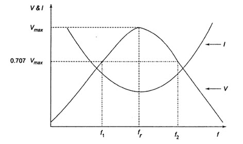
Fig.27.5
\[{\omega _1}={{ - 1} \over {2RC}} + \sqrt {{{\left( {{1 \over {2RC}}} \right)}^2} + {1 \over {LC}}} ...................................................\left( {27.14} \right)\]
Similarly, to obtain the upper half power frequency
\[{\omega _2}C - {1 \over {{\omega _2}L}}={1 \over R}...................................................\left( {27.15} \right)\]
From Eq.27.15, we have
\[{\omega _2}={1 \over {2RC}} + \sqrt {{{\left( {{1 \over {2RC}}} \right)}^2} + {1 \over {LC}}} ...................................................\left( {27.16} \right)\]
Bandwidth \[BW={\omega _2} - {\omega _1}={1 \over {RC}}\]
The quality factor is defined as \[{Q_r}={{{\omega _r}} \over {{\omega _2}{\omega _1}}}\]
\[{Q_r}={{{\omega _r}} \over {1/RC}}={\omega _r}RC\]
In other words,
\[Q=2\pi\times {{\max imum\,\,energy\,\,stored} \over {Energy\,\,dissipated\,\,/\,cycle}}\]
In the case of an inductor,
The maximum energy stored \[={1 \over 2}L{I^2}\]
Energy dissipated per cycle \[={\left( {{I \over {\sqrt 2 }}} \right)^2} \times R \times T\]
The quality factor
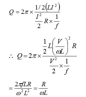
For a capacitor, maximum energy stored = ½ (CV2)
Energy dissipate per cycle \[=P \times T={{{V^2}} \over {2 \times R}} \times {1 \over f}\]
The quality factor
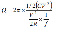
\[=2\pi fCR=\omega CR\]
Last modified: Monday, 30 September 2013, 4:45 AM