Site pages
Current course
Participants
General
Module 1. Average and effective value of sinusoida...
Module 2. Independent and dependent sources, loop ...
Module 3. Node voltage and node equations (Nodal v...
Module 4. Network theorems Thevenin’ s, Norton’ s,...
Module 5. Reciprocity and Maximum power transfer
Module 6. Star- Delta conversion solution of DC ci...
Module 7. Sinusoidal steady state response of circ...
Module 8. Instantaneous and average power, power f...
Module 9. Concept and analysis of balanced polypha...
Module 10. Laplace transform method of finding ste...
Module 11. Series and parallel resonance
Module 12. Classification of filters
Module 13. Constant-k, m-derived, terminating half...
LESSON 29. Classification of pass Band and Stop Band
29.1. Classification of pass Band and Stop Band
It is possible to verify the characteristics of filters from the propagation constant of the network. The propagation constant \[\gamma\], being a function of frequency, the pass band, stop band and the cut-off point, i.e. the point of separation between the two bands, can be identified. For symmetrical T or p-section, the expression for propagation constant \[\gamma\] in terms of the hyperbolic functions is given by Eqs.28.5 and 17.7 in section 28.3. From Eq. 28.7, \[\sinh {\gamma\over 2}=\sqrt {{{{Z_1}} \over {4{Z_2}}}}\]
If Z1 and Z2 are both pure imaginary values, their ratio, and hence Z1/4Z2, will be a pure real number. Since Z1 and Z2 may be anywhere in the range from -j\[\propto\] t0 + j\[\propto\], Z1/4Z2 may also have any real value between the infinite limits. Then \[\sinh \,{\gamma\over 2}=\sqrt {{Z_1}} /\sqrt {4{Z_2}}\] will also have infinite limits, but may be either real or imaginary depending upon whether Z1/4Z2 is positive or negative.
We known that the propagation constant is a complex function \[\gamma\] = \[\alpha\] + jβ, the real part of the complex propagation constant \[\alpha\] , is a measure of the change in magnitude of the current or voltage in the network, known as the attenuation constant. β is a measure of the difference in phase between the input and output currents or voltages, known as phase shift constant. Therefore \[\alpha\] and β take on different values depending upon the range of Z1/4Z2, From Eq. 28.7, we have
\[\sinh {\gamma \over 2}=\,\sinh \left( {{\alpha\over 2} + {{j\beta} \over 2}} \right)=\sinh {\alpha\over 2}\cos {\beta\over 2} + \,\,j\,\,\cosh {\alpha\over 2}\sin {\beta\over 2}\]
\[=\sqrt {{{{Z_1}} \over {4{Z_2}}}} ...................................................\left( {29.1} \right)\]
Case A
If Z1 and Z2 are the same type of reactances, then \[\left[ {{{{Z_1}} \over {4{Z_2}}}} \right]\] is real and equal to say a+x,
The imaginary part of the Eq. 29.1 must be zero.
\[\cosh \,{\alpha\over 2}\sin {\beta\over 2}=0...................................................\left( {29.2} \right)\]
\[\sinh \,{\alpha\over 2}\cos {\beta\over 2}=x...................................................\left( {29.3} \right)\]
\[\alpha\] and β must satisfy both the above equations.
Equation 29.2 can be satisfied if β/2 = 0 or n\[\pi\], where n = 0, 1,2,…, then cos β/2 = 1 and sinh
\[\alpha /2=x=\sqrt {{{{Z_1}} \over {4{Z_2}}}}\]
That x should be always positive implies that
\[\sqrt {{{{Z_1}} \over {4{Z_2}}}}>0\,and\,\alpha=2\,{\sinh ^{-1}}\sqrt {{{Z_1^{}} \over {4{Z_2}}}} ...................................................\left( {29.4} \right)\]
Since \[\alpha\] ≠ 0, it indicates that the attenuation exists.
Case B
Consider the case of Z1 and Z2 being appositive type of reactances, i.e. Z1/4Z2 is negatie, making \[\sqrt {{Z_1}/4{Z_2}}\] imaginary and equal to say jx
The real part of the Eq.29.1 must be zero.
\[\sinh \,{\alpha\over 2}\cos {\beta\over 2}=0...................................................\left( {29.5} \right)\]
\[\cosh \,{\alpha\over 2}\sin {\beta\over 2}=x...................................................\left( {29.6} \right)\]
(i) When \[\alpha\] = 0; from Eq. 29.5, sinh \[\alpha\]/2 = 0. And from Eq.29.6 sin \[\beta /2=x=\sqrt {{Z_1}/4{Z_2}}\] . But the sine can have a maximum value of 1. Therefore, the above solution is valid only for negative Z1/4Z2, and having maximum value of unity. It indicates the conduction of pass band with zero attenuation and follows the condition as
\[- 1 \le {{{Z_1}} \over {4{Z_2}}} \le 0\]
\[\beta=2{\sin ^{-1}}\sqrt {{{{Z_1}} \over {4{Z_2}}}} ...................................................\left( {29.7} \right)\]
(ii) When β = \[\pi\], from Eq.29.5, cos β/2 = . And from Eq.29.6, sinβ/2 = ±1;
cosh a2 = \[x=\sqrt {{Z_1}/4{Z_2}}\] .
Since cosh \[\alpha\]/2 ≥ 1, this solution is valid for negative Z1/4Z2, and having magnitude greater than, or equal to unity. It indicates the condition of stop band since \[\alpha\] = 0.
\[-\alpha\le {{{Z_1}} \over {4{Z_2}}} \le-1\]
\[\alpha=2{\cos ^{-1}}\sqrt {{{{Z_1}} \over {4{Z_2}}}} ...................................................\left( {29.8} \right)\]
It can be observed that there are three limits for case A and B. Knowing the values of Z1 and Z2, it is possible to determine the case to be applied to the filter. Z1 and Z2 are made of different types of reactances, or combinations of reactances, so that, as the frequency changes, a filter may pass from one case to another. Case A and (ii) in case B are attenuation bands, whereas (i) in case B is the transmission band.
The frequency which separates the attenuation band from pass band or vice versa is called cut-off frequency. The cut-off frequency is denoted by ƒc, and is also termed as nominal frequency. Since Z0 is real in the pass band and imaginary in an attenuation band, ƒc is the frequency at which Z0 cahnges from being real to being imaginary. These frequencies occur at
\[{{{Z_1}} \over {4{Z_2}}}=0\,\,or\,\,{Z_1}=0...................................................\left( {29.8a} \right)\]
\[{{{Z_1}} \over {4{Z_2}}}=1\,\,or\,\,{Z_1} + 4{Z_2}=0...................................................\left( {29.8b} \right)\]
The above conditions can be represented graphically, as in Fig. 29.1
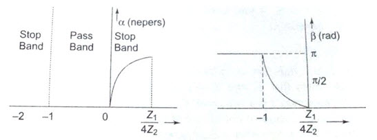
Fig.29.1
29.2. Characteristic Impedance in the Pass and Stop Bands
Referring to the characteristic impedance of a symmetrical T-network, from Eq.28.1 we have
\[{Z_{0T}}=\sqrt {{{Z_1^2} \over 4} + {Z_1}{Z_2}}=\sqrt {{Z_1}{Z_2}\left( {1 + {{{Z_1}} \over {4{Z_2}}}} \right)}\]
If Z1 and Z2 are purely reactive, let Z1 = jx1 and Z2 = jx2, then
\[{Z_{0T}}=\sqrt {{x_1}{x_2}\left( {1 + {{{Z_1}} \over {4{Z_2}}}} \right)} ...................................................\left( {29.9} \right)\]
A pass band exists when x1 and x2 are of opposite reactance and
\[-1 < {{{x_1}} \over {4{x_2}}} < 0\]
Substituting these conditions in Eq.29.9, we find that Z0T is positive and real. Now consider the stop band. A stop band exists when x1 and x2 are of the same type of reactances; then x1/4x2 > 0. Substituting these conditions in Eq.29.9, we find that ZOT is purely imaginary in this attenuation region. Another stop band exists when x1 and x2 are of the same type of reactances, but with x1/4x2 < -1. Then from Eq.29.9, Z0T is again purely imaginary in the attenuation region.
Thus, in a pass band if a network is terminated in a pure resistance R0 (Z0T = R0), the input impedance is R0 and the network transmits the power received from the source to the R0 without any attenuation. In a stop band Z0T is reactive. Therefore, if the network is terminated in a pure reactance (Z0 = pure reactance), the input impedance is reactive, and cannot receiver or transmit power. However, the network transmits voltage and current with 900 phase difference and with attenuation. It has already been shown that the characteristic impedance of a symmetrical p-section can be expressed in terms of T. Thus, from Eq.29.9,
Z0p = Z1Z2/Z0T.
Since Z1 and Z2 are purely reactive, Z0\[\pi\] is real if Z0T is real, and Z0x is imaginary if Z0T is imaginary. Thus the conditions developed for T = sections are valid for \[\pi\] sections.
Last modified: Monday, 30 September 2013, 6:50 AM