Site pages
Current course
Participants
General
Module 1: Basics of Agricultural Drainage
Module 2: Surface and Subsurface Drainage Systems
Module 3: Subsurface Flow to Drains and Drainage E...
Module 4: Construction of Pipe Drainage Systems
Module 5: Drainage for Salt Control
Module 6: Economics of Drainage
Keywords
12 April - 18 April
19 April - 25 April
26 April - 2 May
Lesson 8 Special Drainage Situations
8.1 Drainage of Sloping Land
In earlier lessons, we only considered drainage problems in flat lands. However, some agricultural areas are sloping. Hence, the question arises: can equations for flat lands be applied to sloping lands? When a hillside is drained by a series of parallel drains, the situation is as shown in Fig. 8.1 (Ritzema, 1994). The highest water table height (h), above the drain level is now not midway between the drains, but is closer to the downslope drain.
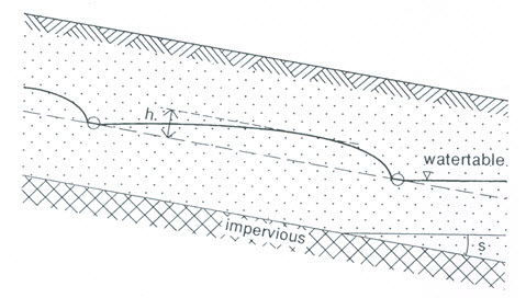
Fig. 8.1. Flow to parallel drains in a homogenous soil overlying a sloping impervious layer. (Source: Ritzema, 1994)
Schmidt and Luthin (1964) solved the hillside seepage problem of steady vertical recharge to parallel ditches penetrating to a sloping impervious layer. The resulting drain spacings for gently sloping areas (slope < 0.1) do not differ much from the drain spacings for flat lands. This is in agreement with the results of Bouwer (1955), who conducted a series of tests in sand-tank models, and the numerical simulations done by Fipps and Skaggs (1989). Because a vast majority of agricultural land will not have slopes more than 0.1, we can apply the solutions obtained for flat lands to sloping lands without any modification as long as the slope is not steeper than 0.1 (Ritzema, 1994).
The above conclusion implies that we assume no difference in efficiency between drains laid parallel or perpendicular to the slope. Where the hydraulic conductivity of the soil is low, it could be advisable to lay the drains parallel to the contour lines, and hence perpendicular to the slope. As the backfilled trenches have and retain a higher permeability than the original soil profile, any surface runoff may possibly be intercepted by the trenches. Further discussion on the layout of subsurface drainage systems in sloping areas is given in Cavelaars et al. (1994).
8.2 Interceptor Drains
Interceptor drains intercept (cutoff) the surface or subsurface flow from higher reaches before such water can encroach upon the cultivated lands and create waterlogging problem. They are also called ‘relief drains’. They can be of open type or buried pipe type. In general, interceptor drains are used for two different purposes (Ritzema, 1994): (a) to intercept seepage water from neighbouring irrigation canals, and (b) to intercept foreign water that seeps down a hill.
The first type of interceptor drains are often installed in irrigated areas parallel to and a short distance away from conveyance canals. To drain such areas, the interceptor drain is frequently installed on both sides of the waterway. Typical interceptor drains in humid areas (Fig. 8.2d) are located above the seepage area where seepage is caused by the shallow depth or outcropping of the impervious layer on the surface. In irrigated regions, the seepage from an
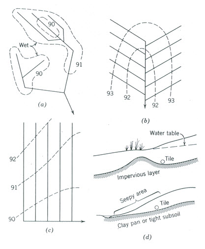
Fig. 8.2. Common types of pipe drainage systems: (a) Natural or random; (b) Herringbone; (c) Gridiron; (d) Cutoff or Interceptor.
(Schwab et al., 2005)
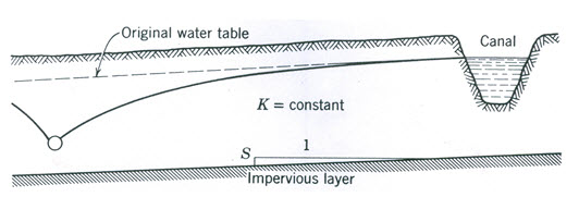
Fig. 8.3 Water table drawdown from an interceptor drain below a canal. (Source: Schwab et al., 2005)
unlined canal, shown in Fig. 8.3, often causes wetness and damage to crops below. The flow towards such a drain is similar to the flow between drains with different water levels. If we assume that there is no recharge from precipitation, we can use the Dupuit Equation to calculate the flow per unit length.
The distance of the first pipe drain below the ditch or canal can be determined by the procedures described by SCS (1973) and USBR (1978). Spacing of drains below the first one are computed from earlier drainage equations, where the land slope is less than 10%. Problems of this type with special boundary conditions can be solved by using computers (Schwab et al., 2005).
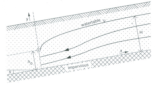
Fig. 8.4. Flow towards an interceptor drain through a homogenous soil overlying a uniformly sloping layer. (Source: Ritzema, 1994)
The second type of interceptor (or hill-side) drainage is shown in Fig. 8.4. Donnan (1959) presented a solution for this type of drainage. He assumed a homogeneous uniform soil layer on top of an impervious layer with a slope. Without an interceptor drain, the slope of the water table will be parallel to the slope of the impervious layer, and hence the amount of seepage water flowing downhill can be calculated by Darcy’s Equation as follows:
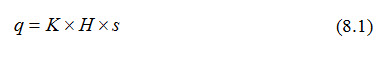
Where, q = flow rate per unit width [L2/T], K = hydraulic conductivity of the top layer [L/T], H = height of the water table above the impervious layer before the installation of the interceptor drain [L], and s = slope of the impervious layer (dimensionless).
If an interceptor drain is constructed at the bottom of the hill at a height h0 above the impervious layer, the slope of the water table in the vicinity of the drain will no longer be parallel to the impervious layer, but will curve towards the drain. With a coordinate system as shown in Fig. 8.4, we can assume that the slope is approximately s + dh/dx. Hence, the amounts of seepage flow through a cross-section at a distance x uphill from the drain is given as (Ritzema, 1994):
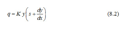
Where, y = height of the water table above the impervious layer at distance x [L], and ![]() = hydraulic gradient at x (dimensionless), and the remaining symbols have the same meaning as defined earlier.
= hydraulic gradient at x (dimensionless), and the remaining symbols have the same meaning as defined earlier.
Because of continuity, the flow with or without the interceptor drain must be equal. That is,
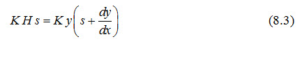
Integrating with y = h0 at x = 0 yields (Donnan, 1959):
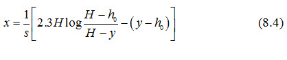
Where, x is the distance uphill from the interceptor drain [L], and the remaining symbols have the same meaning as defined earlier.
Equation (8.4) can be used to calculate the height of the water table at any distance, x uphill from the interceptor drain. Theoretically, y = H is only reached at x = ¥.
Example Problem (Ritzema, 1994): An irrigation scheme (500 m ´ 1000 m) is located in a sloping area (Fig. 8.5). The deep percolation losses are 1 mm/day. The soil consists of a permeable layer, 6 m thick and has a hydraulic conductivity of 2.5 m/day, on top of an impervious layer with a slope of s = 0.04. To control the water table in the area downhill from the irrigated area at a level of 2 m below the soil surface, an interceptor drain will be constructed. Calculate the required depth and capacity of the interceptor drain and the uphill elevation of the water table after the construction of the interceptor drain.
Solution: To control the water table at 2 m below the soil surface, the height of the interceptor drain above the impervious layer (h0) has to be,
h0 = 6.0 - 2.0 = 4.0 m.
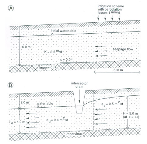
Fig. 8.5. Calculation of an interceptor drain in a sloping area: (A) Before construction; (B) After construction. (Source: Ritzema, 1994)
The percolation losses result in a seepage flow per meter width, which is:
qs = 500 ´ 0.001 = 0.5 m2/day.
The elevation of the water table above the impervious layer before the construction of the interceptor drain can be calculated with using Eqn. (8.1) as:
After the interceptor drain has been constructed, the seepage flow downhill from the drain will be:
qd = K h0 s = 2.5 ´ 4.0 ´ 0.04 = 0.4 m2/day.
Thus, the required capacity of the interceptor drain per meter length (qi) will be:
qi = qs - qd = 0.5 - 0.4 = 0.1 m2/day.
In other words, 20% of the percolating water will be intercepted. As the irrigation scheme is 1000 m long, the discharge at the outlet of the interceptor drain (Qi) will be:
Qi = 1000 ´ qi = 1000 ´ 0.1 = 100 m3/day = 1.16 L/s.
Now, the elevation of the water table uphill from the interceptor drain can be calculated using Eqn. (8.4) as follows:

From the above expression, we have:
At x = 0 m, y = 4.0 m,
At x = 23 m, y = 4.2 m,
At x = 54 m, y = 4.4 m,
At x = 99 m, y = 4.6 m,
At x = 181 m, y = 4.8 m, and
At x = 265 m, y = 4.9 m.
8.3 Artesian Relief Wells
Where artesian aquifers are the main cause of drainage problems, wells may be drilled into the aquifer to reduce the hydrostatic pressure and to lower the water table (Schwab et al., 2005). Sometimes these wells are connected directly into a subsurface drain, thereby allowing the groundwater to flow by gravity rather than by pumping. Water table contour maps or piezometric level contour maps are often required prior to designing such a drainage system.
8.4 Drainage of Heavy Clay Soils
8.4.1 Drainability of Heavy Clay Soils
Heavy clay soils often have such a low hydraulic conductivity that they need very narrow drain spacings. The narrowest spacing applicable in practice is a matter of economics (e.g., crops to be grown, prices of products). The hydraulic conductivity may be so low that no subsurface drainage with economically justifiable spacing is possible. Under such conditions, we should use a surface drainage system of furrows and small ditches, possibly combined with bedding of the soil (Ritzema, 1994).
For moderate soil hydraulic conductivity, it may happen that the infiltration rate is too low for the water to enter the soil so that frequent surface ponding will occur. A suggested limit for the installation of a subsurface drainage system is that the infiltration rate of the soil must be such that the rainfall to be expected in two or three subsequent days must easily infiltrate during that time. If not, a subsurface drainage system will not work satisfactorily and one has to resort to a surface drainage system (Ritzema, 1994).
Heavy clay soils of low hydraulic conductivity often have a top layer with a surprisingly high hydraulic conductivity because of the activity of plant roots or the presence of a tilled layer. In such cases, rainfall will build up a perched water table on the layer just below the top layer (Fig. 8.6). Under such conditions, a subsurface drainage system can be effective because of the interflow in the permeable top layer, but it will only work as long as the backfilled trench remains more permeable than the original soil.
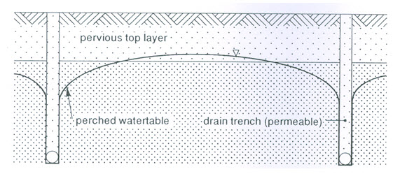
Fig. 8.6. Perched water table built up in heavy clay soil, just below the top layer with a higher hydraulic conductivity. (Source: Ritzema, 1994)
Unless one can expect the hydraulic conductivity of the subsoil to increase with time (e.g., because of the soil ripening process), it makes no sense to install a drainage system at a great depth (Ritzema, 1994). In fact, a system reaching just below the top layer should be sufficient. The system can be improved by filling the trench with coarse material or adding material like lime. Further improvement can be sought in mole drainage, perpendicular to the subsurface lines.
In none of the cases discussed above, it is possible to apply a drainage theory, because the exact flow paths of water are not known (Ritzema, 1994). Also, these heavy soils often have a seasonal variation in hydraulic conductivity because of swelling and shrinking.
8.4.2 Mole Drain: A Promising Solution
Mole drain (Fig. 8.7a) is a temporary method of drainage for heavy clay soils. It is also known as a pipeless drain. Where soil conditions are favorable, mole drains function efficiently for the first few years and then gradually deteriorate. Mole drains have been successful in England, New Zealand, and several European countries. Their maximum life is 10 to 30 years (Schwab et al., 2005). Mole drains are unlined cylindrical channels of about 10 cm (normal range is 5 to 10 cm) in diameter, which are artificially created in the subsoil without digging a trench from the surface. They are constructed at a depth shallower than one meter (usually 40 to 60 cm) to work as a subsurface drain by intercepting gravitational soil-water and conveying it towards the drain outlet. The mole drain outlets are protected by installing a rigid pipe for the last about 2 m length of the mole drain, protruding out sufficiently to permit a clear overfall of drainage effluent without disturbing the soil around the downstream end of the mole drain. Mole drains are constructed using a mole plough (Fig. 8.7b) which is comprised of a rigid vertical bar of thin front edge to reduce resistance to soil shearing when it is pulled by a tractor, a plough fitted to the lower end of the vertical bar, and a conduit opener in the shape of a bullet. The bullet is attached to the plough and creates a cylindrical channel as the mole plough is pulled forward by a tractor. In order to have stable mole drains, the soil must be cohesive, with a greater percentage of clay (Jha and Koga, 2002).
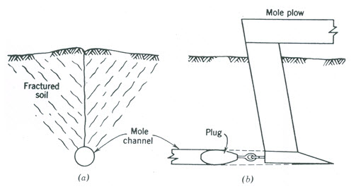
Fig. 8.7(a,b). Schematic diagram of mole drainage: (a) Cross-section of a mole channel showing cracks around it; (b) Profile of a mole plough.(Source: Schwab et al., 2005)
If mole drains are constructed at suitable soil moisture content, the shearing effect on the soil in the vicinity of the rigid bar and the mole plough extends one to two meters on either side, forming cracks around mole channels (Fig. 8.7a) which facilitate gravitational water movement towards the mole channels. The soil moisture content at the time of moling plays an important role in crack formation, mole channel stability, and power requirement to pull the mole plough. If the soil is too wet, cracks may not develop properly, the internal mole surface will get smeared and will not permit adequate transfer of gravitational water in the soil profile across the mole surface, and the mole channel may collapse rapidly. On the other hand, if the soil is too dry, cracks will develop but the power requirement will be too large and the mole may also collapse due to the dislodgement of relatively drier soil particles at the inner mole surface. The appropriate moisture content to construct mole drains is judged from experience. A general guideline in this respect is that the soil moisture content should be between the Liquid Limit and the Plastic Limit (Bhattacharya and Michael, 2003). Besides the moisture content, the bulk density of the soil is also an important factor governing the power requirement and the crack formation during moling. If the soil above the mole drain is less pervious, subsoiling helps in developing wider path for the shallow soil water to flow towards the mole drain.
In India, there is more than 76 Mha of heavy clay/clay soils, of which about 69 Mha is distributed (in decreasing order of the area) in the states of Maharastra, Madhya Pradesh, Gujarat, Andhra Pradesh and Karnataka, and about 7 Mha is distributed (in decreasing order of the area) in the states of Tamil Nadu, Rajasthan, Orissa and Bihar (Bhattacharya and Michael, 2003). Some of these soils are suitable for mole drainage. An excellent review of the theory and practice of mole drainage is presented by Jha and Koga (2002), while a case study on the performance evaluation of mole drainage in Bangkok clay soils is reported in Jha and Koga (1995).
References
Bhattacharya, A.K. and Michael, A.M. (2003). Land Drainage: Principles, Methods and Applications. Konark Publishers Pvt. Ltd., New Delhi, India.
Bouwer, H. (1955). Tile drainage of sloping fields. Agricultural Engineering 36.
Cavelaars, J.C., Vlotman, W.F. and Spoor, G. (1994). Subsurface Drainage Systems. In: H.P.Ritzema (Editor-in-Chief), Drainage Principles and Applications, International Institute for Land Reclamation and Improvement (ILRI), ILRI Publication 16, Wageningen, The Netherlands, pp. 827-929.
Donnan, W.W. (1959). Drainage of agricultural land using interceptor lines. Journal of the Irrigation and Drainage Division, ASCE, pp. 13-23.
Fipps, G. and Skaggs, R.W. (1989). Influence of slope on subsurface drainage of hillsides. Water Resources Research, 25(7): 1717-1726.
Jha, M.K. and Koga, K. (1995). Mole drainage: Prospective drainage solution to Bangkok clay soils. Agricultural Water Management, 28(3): 253-270.
Jha, M.K. and Koga, K. (2002). Design and practice of pipeless drainage systems: A review. International Agricultural Engineering Journal, 11(2&3): 59-91.
Ritzema, H.P. (1994). Subsurface Flow to Drains. In: H.P.Ritzema (Editor-in-Chief), Drainage Principles and Applications, International Institute for Land Reclamation and Improvement (ILRI), ILRI Publication 16, Wageningen, The Netherlands, pp. 294-304.
Schmidt, P. and Luthin, J.N. (1964). The drainage of sloping lands. Journal of Geophysical Research, 69: 1525-1529.
Schwab, G.O., Fangmeier, D.D., Elliot, W.J. and Frevert, R.K. (2005). Soil and Water Conservation Engineering. Fourth Edition, John Wiley and Sons (Asia) Pte. Ltd., Singapore.
SCS (1973). Drainage of Agricultural Lands. U.S. Soil Conservation Service, Water Information Center Inc., Port Washington, NY.
USBR (1978). Drainage Manual. U.S. Bureau of Reclamation, GPO, Washington, DC.
Suggested Readings
Murty, V.V.N. and Jha, M.K. (2011). Land and Water Management Engineering. Sixth Edition, Kalyani Publishers, Ludhiana, India.
Ritzema (Editor-in-Chief) (1994). Drainage Principles and Applications. International Institute for Land Reclamation and Improvement (ILRI), ILRI Publication 16, Wageningen, The Netherlands.
Smedema, L.K. and Rycroft, D.W. (1983). Land Drainage. Batsford Academic and Education Ltd., London.
Schwab, G.O., Fangmeier, D.D., Elliot, W.J. and Frevert, R.K. (2005). Soil and Water Conservation Engineering. Fourth Edition, John Wiley and Sons (Asia) Pte. Ltd., Singapore.
Last modified: Monday, 16 September 2013, 10:48 AM