Site pages
Current course
Participants
General
Module 1: Basics of Agricultural Drainage
Module 2: Surface and Subsurface Drainage Systems
Module 3: Subsurface Flow to Drains and Drainage E...
Module 4: Construction of Pipe Drainage Systems
Module 5: Drainage for Salt Control
Module 6: Economics of Drainage
Keywords
12 April - 18 April
19 April - 25 April
26 April - 2 May
Lesson 9 Materials for Pipe Drainage Systems
9.1 Materials for Drain Pipe
The materials used for manufacturing drain pipes are clay, concrete, and plastics. Important criteria for pipe quality and for selecting the most suitable type of pipes are: resistance to mechanical and chemical damage, longevity, and costs (Cavelaars et al., 1994). Mechanical damage and chemical deterioration may occur during transport and handling, or after the pipe has been installed. In addition, the lifetime of the pipes should not be excessively shortened by deterioration in mechanical or chemical properties in the course of time. The costs are the total costs for purchase, transport, handling, and installation.
9.1.1 Clay Tiles
Clay tiles used to be predominant type of drain pipes in Europe, from the first introduction of pipe drainage (before 1850), to about 1960-1970 (Cavelaars et al., 1994). Clay tiles were made from clay, shale, fireclay or mixture thereof and burnt (IS, 1983). These clay tiles had common diameters of 0.05 to 0.15 m, and came in lengths of 0.30 to 0.33 m. Their ends were either straight or had a collar, with a less-than-perfect fit so that the water could enter through the joints. The chemical stability and longevity of good-quality pipes are excellent.
Criteria for testing the quality of clay pipes are (Cavelaars et al., 1994): shape (they should be straight, with straight-cut ends), absence of fissures and cracks (which can be judged by the sound when the pipe is hit), and mechanical strength (breaking strength). Moreover, the tiles should be uniformly burnt and should be free from minerals and chemicals that are known to cause slaking or disintegration of tiles (IS, 1983). The manufacture of good-quality pipes requires considerable skill and a fairly large well-equipped production unit.
9.1.2 Concrete Pipes
Concrete pipes were used as field drains like clay tiles in various countries, until they virtually became obsolete with the introduction of plastic pipes (Cavelaars et al., 1994). In larger diameters, concrete pipes are still commonly used as collectors. Concrete pipes (Fig. 9.1) can be manufactured in comparatively simple (mobile) production units that can easily be erected in the project area. There is practically no limit to their diameter, although for large diameters (i.e., >0.4 m), the concrete must be reinforced (Cavelaars et al., 1994). Pipe ends are either straight, have a collar, or a spigot-and-groove. Water entry is almost exclusively through the joints between pipe sections. For larger diameters, openings at the joints may become rather large; this is the reason that some manufacturers supply rubber sealing rings.
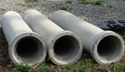
Fig. 9.1. Reinforced concrete drain pipes.
(Source: http://www.marieturnerinc.com)
Possible disadvantages of concrete pipes are their susceptibility to acidity and sulphate, which may be present in the soil. This susceptibility can be reduced to some extent with the use of sulphate-resistant cement, and by producing to a high manufacturing standard so that high-density concrete is formed which seals off the concrete from attack by soil chemicals (Cavelaars et al., 1994).
9.1.3 Plastic Pipes
The introduction of plastic pipes for drainage started around 1960. Initially, straight-walled smooth pipes (Fig. 9.2a) were used. Around 1970, corrugated pipes (Fig. 9.2b) were introduced, which soon replaced the smooth pipes (Cavelaars et al., 1994). The major advantages of plastic over clay or concrete are the much lower weight per meter of pipe, and the greater length of pipe (at least several meters). This makes transporting and handling the pipes a lot easier and cheaper, and it enables higher installation rates. A disadvantage is the environmental pollution caused by the raw material (resin). Ex-factory prices of plastic pipes may be higher than that for clay or concrete pipes, but the total costs may be lower because of a saving in the costs of transport, handling and installation.
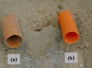
Fig. 9.2. Plastic drain pipes: (a) Smooth pipe; (b) Corrugated pipe.
(Source: http://www.theimagefile.com/v/tp/130/263/1862791002_4_farming-drainage-agriculture.jpg)
The three predominant materials for plastic pipes are (Cavelaars et al., 1994): polyvinyl chloride (PVC), high-density polyethylene (HDPE) (Fig. 9.3), and, to a minor extent, polypropylene (PP). When comparing PVC and HDPE, one can find that the dark-colored HDPE is more affected by high temperatures than the light-colored PVC. Consequently, the risk of deformation for HDPE pipes is greater than for PVC pipes.
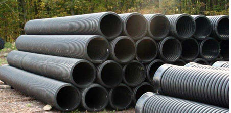
Fig. 9.3. High-density polyethylene (HDPE) drain pipes.
(Source: http://www.marieturnerinc.com)
On the other hand, PVC, being more sensitive to low temperatures, becomes brittle when exposed to temperatures below freezing point. In addition, PVC is more sensitive to ultra-violet radiation (sunshine), which may cause irreversible deterioration of mechanical properties (brittleness). Therefore, PVC pipes should not be stored in bright sunlight. PVC has some environmental disadvantages also because it forms hydrochloric acid when burnt (FAO, 2005). Note that plastic pipes (PVC, HDPE, or PP) are resistant to all chemicals that may occur in agricultural soils.
9.2 Drain Envelopes
When a subsurface drain is installed, some soils may require measures to protect the drain pipe from soil particle entry. Due to the drag force of the water, soil particles or aggregates may be carried into the pipe through the perforations in the pipe wall. This process can never be prevented completely, but it may substantially be slowed down or partially stopped by the use of external porous material around the drain pipe. The porous material designed to do this job is called ‘drain envelope’ (FAO, 2005). A variety of terms are used for drain envelopes, reflecting its purpose and method of application. Commonly used terms are: filter, cover material, and permeable fill. However, the term ‘drain envelope’ has often erroneously been referred to as a ‘drain filter’ (FAO, 2005).
In the subsequent sub-sections, the discussion on drain envelopes is provided in terms of their requirement, functions, design criteria, and construction materials.
9.2.1 Requirement of Drain Envelopes
Qualitative guidelines for designing drain envelopes mainly consider soil texture. Straightforward rules can be given for fine-textured and coarse-textured soils. However, for soils in the intermediate texture classes, there is a considerable uncertainty.
Fine-textured soils with a clay content of more than about 0.25 to 0.30 are characterized by a high structural stability, even if being worked under wet conditions (Cavelaars et al., 1994). Thus, with trencher-installed pipe drains, no problems are to be expected and a drain envelope is not required. However, with trenchless drainage, one can easily work below the critical depth, especially in wet conditions, resulting in a high entrance resistance. A drain envelope is not likely to be of any help. Clogging of the pipe is not to be expected.
On the other hand, coarse-textured soils free of silt and clay are permanently unstable, even if undisturbed. Thus, soil particles are likely to wash into the pipe, both from the trench backfill and from the undisturbed soil below the pipe. There is a need for a permanent drain envelope, completely surrounding the pipe, only as an effective filter, because there is no high entrance resistance. In this case, a thin geotextile envelope is probably the best solution (Cavelaars et al., 1994).
Soils of intermediate texture are not so simple. In the finer-textured soils of this category (clay contents less than 0.25 to 0.30, but more than say 0.10 to 0.15), the trench backfill will remain stable and of good permeability, provided that pipe installation is done under dry conditions and in irrigated land, provided that the trench backfill is properly compacted (Cavelaars et al., 1994). In these cases, even without an envelope, no problems will arise. However, if the pipes are installed under wet conditions, both drain sedimentation and a high entrance resistance can follow. Hence, a drain envelope is required in this case. A commonly applied guideline in The Netherlands is that the drain envelope should be ‘voluminous’ in order to fulfill its hydraulic function. Nevertheless, a thin filter sheet wrapped around a corrugated pipe will do the job equally well, because it ensures that water is conveyed towards the perforations (Cavelaars et al., 1994). It should be noted that a drain envelope, in spite of its general positive effect, is no guarantee against poor drain-line performance, especially when the pipes are installed under wet conditions.
9.2.2 Functions of Drain Envelopes
A drain envelope is defined as the material placed around pipe drains to perform one or more of the following functions (Cavelaars et al., 1994):
Filter function: to prevent or restrict soil particles from entering the pipe where they may settle and eventually clog the pipe;
Hydraulic function: to constitute a medium of good permeability around the pipe and thus reduce entrance resistance;
Bedding function: to provide-all-round support to the pipe in order to prevent damage due to the soil load. Note that large diameter plastic pipes are embedded in gravel especially for this purpose.
The first two functions provide a safeguard against the two main hazards of poor drain-line performance, viz., siltation and high flow resistance in the vicinity of drains.
9.2.3 Design Criteria
In view of drain-envelope functions, ideally, the drain envelope should be designed in such a way that it prevents the entry of soil particles into the pipe, though a limited flow of clay particles will do little harm, because they mainly leave the pipe in suspension. The filtering effect, however, should not be such that the envelope, while keeping the pipe free from sediment, itself becomes clogged. If this happens, the hydraulic function of the drain envelope is severely affected. Besides these conflicting filtering and hydraulic functions, the formulation of functional criteria for the design of envelopes is complicated by a dependence on soil characteristics (mainly soil texture) and drain installation conditions as mentioned earlier. In spite of considerable research efforts, firm quantitative criteria are still far from established. Instead, to a large extent, drainage practice works with qualitative, empirical guidelines (Cavelaars et al., 1994).
The standard procedure for the design of gravel envelopes is to match the particle-size distribution of the soil with the particle-size distribution of the gravel. Several sets of design criteria to prevent base soil invasion into the drain envelope and the drain pipe have been developed such as Soil Conservation Services (SCS) and United States Bureau of Reclamation (USBR) criteria (Cavelaars et al., 1994). In these standards, the underlying requirements are that the drain envelope should fulfill both the filter and the hydraulic function, that particles from the drain envelope itself should not move through the perforations into the drain in significant amounts, and that the drain envelope should not contain very coarse particles which could possibly damage the pipe during placement. The general procedure for designing a gravel envelope for a given soil is as follows (FAO, 2005):
(1) Make a particle-size analysis of both the soil and the proposed gravel envelope;
(2) Compare the two particle-size distribution curves; and
(3) Decide, by some design criterion, whether the proposed gravel envelope material is suitable.
Gravel is available in many countries and has proven to be a suitable drain envelope if properly installed. Nevertheless, although modern drainage machinery has facilities to install gravel automatically under and around the pipe, it remains a costly and difficult operation (Cavelaars et al., 1994).
9.2.4 Envelope Materials
A wide variety of materials are used as envelopes for drain pipes ranging from organic and mineral material to synthetic material and mineral fibers (Cavelaars et al., 1994). Organic material is mostly fibrous, and includes peat (the classical material used in Western Europe), coconut fiber (Fig. 9.4a), and various organic waste products like straw, chaff, heather, and sawdust. Mineral materials are mostly used in a granular form; they may be gravel, slag of various kinds (industrial waste products), or fired clay granules. Synthetic materials may be in a granular form (e.g., polystyrene) or in a fibrous form [e.g., nylon, acryl, and polypropylene (Fig. 9.4b)]. Mineral fibers such as glass fiber, glass wool, and rock wool, are also used.
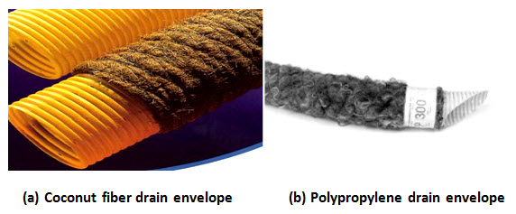
Fig. 9.4. Drain-envelope materials: (a) Coconut fiber; (b) Polypropylene. (Source: FAO, 2005)
Envelope materials are applied in bulk, as thin sheets (Fig. 9.5), or as more voluminous ‘mats’ (Cavelaars et al., 1994). Bulk application is common for gravel, peat litter, various slags, and granules. The classical method is to spread the material after the pipe has been laid in the trench so that the material will protect the top and the sides of the pipe. A complete surround (e.g., with gravel) is achieved by first spreading gravel on the trench bottom, then lying the pipe, and again spreading gravel.
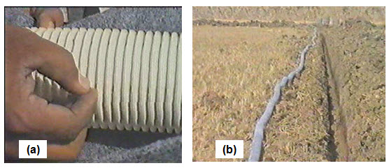
Fig. 9.5. Application of geo-textile envelope material: (a) Corrugated perforated PVC pipe being wrapped with geo-textile envelope material; (b) Lateral drain pipe wrapped with geo-textile envelope material is ready for installation. (Source: Indo-Dutch/APWAM Project, ANGRAU)
Many of the drawbacks of gravel envelopes can be overcome with the use of synthetic envelopes. Thin sheets are commonly used with corrugated plastic pipe as a pre-wrapped envelope. They may consist of glass fibre or synthetic fibres, which are also known as geotextiles. More voluminous mats of up to about 10 mm thick normally consist of fibrous materials, whether they are organic materials, synthetic fiber, or mineral fiber (Cavelaars et al., 1994). These mats are often used as pre-wrapped envelopes with plastic pipes, but they can also be used in the form of strips. One such a strip may be placed only on top of the pipe, or another strip may be placed below the pipe, thereby making it suitable in combination with any type of pipe (clay, concrete, or plastic).
References
Cavelaars, J.C., Vlotman, W.F. and Spoor, G. (1994). Subsurface Drainage Systems. In: H.P. Ritzema (Editor-in-Chief), Drainage Principles and Applications, ILRI Publication 16, International Institute for Land Reclamation and Improvement (ILRI), Wageningen, The Netherlands, pp. 827-929.
FAO (2005). Materials for Subsurface Land Drainage Systems. Irrigation and Drainage Paper 60, Chapter 3, Food and Agriculture Organization (FAO), Rome, ftp://ftp.fao.org/agl/aglw/docs/idp60.pdf (accessed on May 02, 2013).
IS (1983). Specification for Farm Drainage Clay Tiles. Indian Standards Institution, IS: 8967 – Part-2, Indian Standard (IS), New Delhi, India, http://archive.org/stream/gov.law.is.8967.2.1983/is.8967.2.1983#page/n2/mode/1up (accessed on May 04, 2013).
Suggested Readings
Bhattacharya, A.K. and Michael, A.M. (2003). Land Drainage: Principles, Methods and Applications. Konark Publishers Pvt. Ltd., New Delhi, India.
Murty, V.V.N. and Jha, M.K. (2011). Land and Water Management Engineering. Sixth Edition, Kalyani Publishers, Ludhiana, India.
Ritzema (Editor-in-Chief) (1994). Drainage Principles and Applications. International Institute for Land Reclamation and Improvement (ILRI), ILRI Publication 16, Wageningen, The Netherlands.
Schwab, G.O., Fangmeier, D.D., Elliot, W.J. and Frevert, R.K. (2005). Soil and Water Conservation Engineering. Fourth Edition, John Wiley and Sons (Asia) Pte. Ltd., Singapore.
Smedema, L.K. and Rycroft, D.W. (1983). Land Drainage. Batsford Academic and Education Ltd., London.
Last modified: Monday, 16 September 2013, 11:03 AM