Site pages
Current course
Participants
General
Module 1_Fundamentals of GW
Module 2_Well Hydraulics
Module 3_Design, Installation and Maintenance of W...
Module 4_Groundwater Assessment and Management
Module 5_Principle, Design and Operation of Pumps
Module 6_Performance Characteristics, Selection an...
Keywords
12 April - 18 April
19 April - 25 April
26 April - 2 May
Lesson 17 Methods for Constructing Shallow Wells
17.1 Introduction
Different types of water wells are discussed in Lesson 8. For the construction point of view, water wells can be grouped under two categories: (a) Shallow wells, and (b) Deep wells. Shallow water wells can be either open wells or tubewells and are generally less than 15 m in depth. Deep water wells are usually tubewells and they are greater than 15 m in depth. However, in practice the terms ‘shallow’ and ‘deep’ are used in a relative sense and their depth limits vary considerably from one region/country to another. In this lesson, different methods of construction for shallow wells are described, while the methods of construction for deep wells are discussed in Lesson 18.
There are a variety of techniques for constructing water wells. Selection of a suitable method for well construction depends on the factors such as geologic conditions, purpose of the well, diameter and depth of the well, production capacity of the well, volume of work, maintenance, and availability of funds (Todd, 1980; Michael and Khepar, 1999; Raghunath, 2007). Shallow groundwater wells (<15 m deep) are constructed by digging, boring, driving, or jetting. Table 17.1 presents an extensive summary of the applications of these methods, together with the drilling methods used for constructing deep wells (>15 m deep). A brief description of digging, boring, driving and jetting methods is provided in the subsequent sections. Drilling methods/techniques are described in Lesson 18.
Table 17.1. Methods of well construction and their suitability
(Source: Todd, 1980)
|
Well Construction Method |
Most Suitable Materials |
Most Suitable Water Table Depth (m) |
Usual Maximum Depth (m) |
Normal Range of Diameter (cm) |
Usual Casing Material |
Customary Use |
Well Yield (m3/day) |
Remarks |
|
1.Augering (a) Hand Auger |
Clay, silt, sand, gravel (<2 cm) |
2-9 |
10 |
5-20 |
Sheet metal |
Domestic, drainage |
15-250 |
Most effective for penetrating and removing clay. Limited by gravel over 2 cm. Casing required if material is loose. |
|
(b) Power Auger |
Clay, silt, sand, gravel less than 5 cm |
2-15 |
25 |
15-90 |
Concrete, steel or wrought-iron pipe |
Domestic, irrigation, drainage |
15-500 |
Limited by gravel over 2 cm, otherwise same as for the hand augers. |
|
2. Driving (Hand, Air Hammer) |
Silt, sand, gravel less than 5 cm |
2-5 |
15 |
3-10 |
Standard weight pipe |
Domestic, drainage |
15-200 |
Limited to shallow water table, no large gravel. |
|
3. Jetting (Light, Portable Rig) |
Silt, sand, gravel less than 2 cm |
2-5 |
15 |
4-8 |
Standard weight pipe |
Domestic, drainage |
15-150 |
Limited to shallow water table, no large gravel. |
|
4. Drilling (a) Cable Tool |
Unconsoli-dated and consolidated medium hard and hard rocks |
Any Depth |
450b |
8-60 |
Steel or wrought-iron pipe |
All uses |
15-15,000 |
Effective for water exploration. Requires casing in loose materials. Mud-scow and hollow rod bits developed for drilling unconsolidated fine to medium sediments |
|
(b) Rotary |
Silt, sand, gravel less than 2 cm; soft to hard consolidated rocks |
Any Depth |
45b |
8-45 |
Steel or wrought-iron pipe |
All uses |
15-15,000 |
Fastest method for all except hardest rock. Casing usually not required during drilling. Effective for gravel envelope wells. |
|
(c) Reverse Circulation Rotary |
Silt, sand, gravel, cobble |
2-30 |
60 |
40-120 |
Steel or wrought-iron pipe |
Irrigation, industrial, municipal |
2500-20,000 |
Effective for large- diameter holes in unconsolidated and partially consolidated deposits. Requires large volume of water for drilling. Effective for gravel envelope wells. |
|
(d) Rotary Percussion |
Silt, sand, gravel less than 5 cm; soft to hard consolidated rock |
Any depth |
600b |
30-50 |
Steel or wrought-iron pipe |
Irrigation, industrial, municipal |
2500-15,000 |
Now used in oil exploration. Very fast drilling. Combines rotary and percussion methods (air drilling); cuttings removed by air. Would be economical for deep water wells. |
Note: aYield influenced mainly by the geology and availability of groundwater; bGreater depths reached with heavier equipment.
17.2 Digging
A pick and shovel are the basic implements for digging open wells in shallow aquifers. Loose material is brought to the surface in a container by means of rope and pulleys. Large dug wells can be constructed rapidly with portable excavating equipment such as clamshell and orange-peel buckets. For safety and to prevent caving, lining of wood or sheet piling should be placed in the hole to brace the walls (Todd, 1980; Michael and Khepar, 1999).
The depth of a dug well may be up to 20 m or more depending on the position of the water table, with the well diameter usually ranging from 1 to 10 m. Fig. 17.1 shows a typical dug well which is permanently lined with a casing/curb of wood staves, brick, rock, concrete or metal. The curb is perforated for entry of water and is firmly seated at the bottom. Gravel is backfilled around the curb and at the bottom of the well to control sand entry and possible caving. A properly constructed dug well penetrating a permeable aquifer can yield 2500 to 7500 m3/day, although most domestic dug wells yield less than 500 m3/day (Todd, 1980). Dug wells are generally used for individual water supplies in areas containing unconsolidated glacial and alluvial deposits. Further details of open-well (dug well) construction in alluvial and hard rock formations can be found in Michael and Khepar (1999).
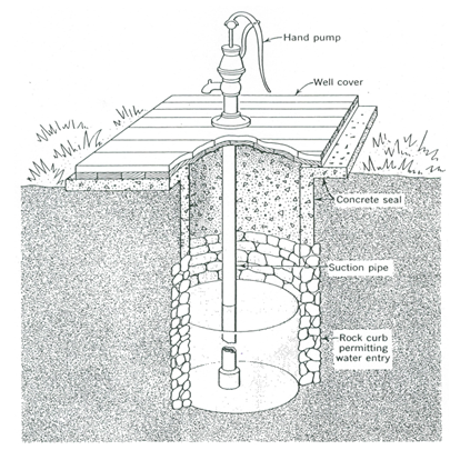
Fig.17.1. Typical domestic dug well with a rock curb, concrete seal and hand pump. (Source: Todd, 1980)
17.3 Boring
Augers are generally used for boring a well in shallow and unconsolidated aquifers. They are most suitable for the formations which don’t cave. Augers are of two types: (a) Hand-operated augers, and (b) Power-driven augers.
17.3.1 Hand-Operated Augers
As shown in Fig. 17.2(a), hand-operated augers have cutting blades at the bottom that bore into the ground with a rotary motion. When the blades are full of loose earth, the auger is removed from the hole and emptied.
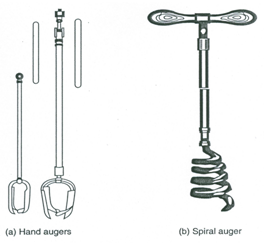
Fig. 17.2. Augers for boring wells: (a) Hand augers; (b) Spiral auger. (Source: Raghunath, 2007)
This procedure is repeated until the desired hole depth is reached. On the other hand, a spiral auger [Fig. 17.2(b)] is used to remove stones or boulders encountered during boring. Hand-bored wells can be up to 20 cm in diameter and 15 m in depth (Todd, 1980).
17.3.2 Power-Driven Augers
Power-driven auger consists of a cylindrical steel bucket with a cutting edge projecting from a slot in the bottom (Fig. 17.3). The bucket is filled up by rotating it in the hole by a drive shaft of adjustable length. When the container is full of excavated material, the auger is raised and emptied with the help of hinged openings located on the side or bottom of the bucket. Reamers, attached to the top of the bucket, help in enlarging holes to diameters exceeding the auger size. Power-driven augers can bore holes up to 1 m in diameter and to depths greater than 30 m (Todd, 1980).
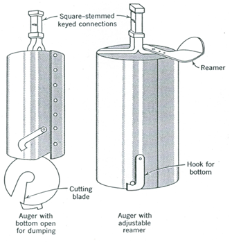
Fig. 17.3. Power-driven augers (Source: Todd, 1980).
There is another kind of power-driven auger called Continuous-flight power auger which has a spiral extending from the bottom of the hole to the surface. A screw conveyer is provided to carry the cuttings to the surface and the sections of the auger can be added as the depth increases. It is usually truck-mounted and can be operated by one person and can bore up to depths more than 50 m in unconsolidated formations devoid of large boulders. Note that where sticky clay formations are encountered, augers supplement other well-drilling methods because augers are more effective than any other penetrating device under such conditions.
17.4 Driving
In this method of well construction, a series of connected lengths of pipe is driven by repeated impacts into the ground to depths below the water table. Water enters the well through a drive point at the lower end of the well. A driven well with its driving mechanism is shown in Fig. 17.4. This consists of a screened cylindrical section protected during driving by a steel cone at the bottom. Driving can be done with a sledge, drop hammer or air hammer. The diameters of driven wells are in the range of 3 to 10 cm, and their depths are usually less than 15 m although a few wells exceed 20 m depth (Todd, 1980). Suction-type pumps are used to extract water from driven wells.
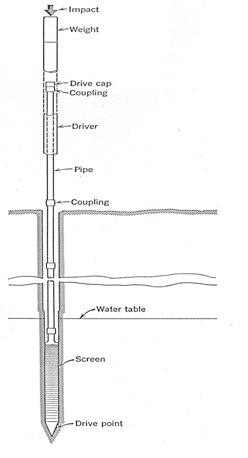
Fig. 17.4. A driven well with driving mechanism. (Source: Todd, 1980)
Driven wells can be installed only in unconsolidated formations which are relatively free of large gravels or rocks. The yield of driven wells is generally about 100-250 m3/day (Todd, 1980). Driven wells are mostly used for domestic water supplies, temporary water supplies, and for exploration and observation. A series of driven wells connected by a suction header to a single pump is known as a well-point system which is used for dewatering excavations for foundations and other subsurface construction works. The main advantages of driven wells are that they can be constructed in a short time, at minimum cost, and even by one person.
17.5 Jetting
Jetted wells are constructed by the cutting action of a downward directed stream of water. The force of high velocity stream or jet of fluid loosens the subsurface materials and transports them upward and out of the hole. Jetting (Jet drilling) is achieved by a chisel-shaped bit attached to the lower end of a pipe string. Holes on each side of the bit serve as nozzles and water jets through these nozzles keep the bit clean and help loosen the material being drilled. Various types of jetting drill bits are shown in Fig. 17.5.
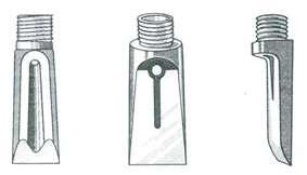
Fig. 17.5. Types of jetting drill bits. (Source: Todd, 1980)
A tripod and pulley, winch and a small pump of approximately 680 L/min at a pressure of 3.5 to 5 kg/cm2 is used to force the drilling fluid (often normal water and in special cases, soft mud) through a hose on to the drill pipe and bit as shown in Fig. 17.6. During the jetting operation, the drill pipe is turned slowly to ensure a straight hole. When the casing extends to below the water table, the well pipe with screen attached is lowered to the bottom of the hole inside the casing. The outer casing is then removed, gravel is inserted in the outer space, and the shallow jetted well is completed.
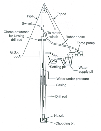
Fig. 17.6. Water jet method. (Source: Raghunath, 2007)
Jetting method is suitable for unconsolidated formations and can produce small- diameter holes of 3 to 10 cm to depths greater than 15 m (Todd, 1980). Jetted wells have only small yields, and are useful for exploratory test holes, observation wells and well-point systems.
References
-
Michael, A.M. and Khepar, S.D. (1999). Water Well and Pump Engineering. Tata McGraw-Hill Publishing Co. Ltd., New Delhi.
-
Raghunath, H.M. (2007). Ground Water. Third Edition, New Age International Publishers, New Delhi.
-
Todd, D.K. (1980). Groundwater Hydrology. John Wiley & Sons, New York.
Suggested Readings
-
Todd, D.K. (1980). Groundwater Hydrology. John Wiley & Sons, New York.
-
Raghunath, H.M. (2007). Ground Water. Third Edition, New Age International Publishers, New Delhi.
-
Michael, A.M. and Khepar, S.D. (1999). Water Well and Pump Engineering. Tata McGraw-Hill Publishing Co. Ltd., New Delhi.
-
Sarma, P.B.S. (2009). Groundwater Development and Management. Allied Publishers Pvt. Ltd., New Delhi.
Last modified: Friday, 14 March 2014, 11:24 AM