Site pages
Current course
Participants
General
Module 1:Water Resources Utilization& Irrigati...
Module 2:Measurement of Irrigation Water
Module 3: Irrigation Water Conveyance Systems
Module 4: Land Grading Survey and Design
Module 5: Soil –Water – Atmosphere Plants Intera...
Module 6: Surface Irrigation Methods
Module 7: Pressurized Irrigation
Module 8: Economic Evaluation of Irrigation Projec...
19 April - 25 April
26 April - 2 May
LESSON 24 Soil Water Constants
24.1 Soil Moisture Constants
In the previous lecture (21) we have discussed the types of soil water and also measures of water content in the soil. From previous discussion, it is clear that a part of capillary water is useful for plant uptake and thus we need to replenish this part of soil water during irrigation. In order to manage irrigation, we need to define soil water constants that are used as reference points for practical irrigation water management. These constants are briefly explained below:
24.1.1 Saturation Capacity
Saturation capacity of soil refers to the condition when all the macro and micropores are filled with water and the soil is at maximum water retention capacity (Fig. 24.1).The metric suction at this condition is almost zero and it is equal to free water surface.
24.1.2 Field Capacity
The field capacity is the amount ofwater held in soil after excess water has been gravity drained and the rate of downwardmovement has relatively stable, which usually takes place within 1 – 3 days after a rain or irrigation. At fieldcapacity, the soil moisture tension depending on the soil texture ranges from 0.10 to 0.33bars. Field capacity is the upper limit of available soilmoisture. The field capacity is greatly influenced by soiltexture, finer the soil particles higher the water retention due to very large surface areaand vice versa. It can be seen from Table 2.1 that moisture content at field capacity of clay soil is much higher (40%) as compared to that of coarse sand (10%).
Field capacity of soil can be determined by ponding water over the area of 2 to 5m2 for two to three days, with surface evaporation prevented by spreading polyethylene sheet on thick straw mulch over the soil surface. After three days soil samples from different depth will give the field capacity. As a rule of thumb, 1 day of drainage will generally be adequate for sandy soils,2 days for silt loam soils, and 3 days for silty clay loam soils.
24.1.3 Permanent Wilting Point
Permanent wilting point is considered as lower limit of available soil moisture. At this stage, water is held tightly by the soil particlesthat the plant roots can no longer obtain enough water to satisfythe transpiration requirements; and remain wilted unless the moisture replenished. The soil moisture tension atpermanent wilting point is about 15 bars.
24.1.4 Available Soil Moisture
Available soil moisture is the moisture between field capacity (0.33 bars) andpermanent wilting point (15 bars) which is referred as readily available water (TAW) for plant growth. The water present above the field capacity and below the permanent wilting point is not available to the plant. The available soil moisture is expressed as depth of water per unit of soil and is calculated according the following formula:
![]() (24.1)
(24.1)
Where,
TAW = Total available water (cm)
ΘFC = Volumetric moisture content at field capacity (fraction)
ΘPWP = Volumetric moisture content at Permanent wilting point (fraction)
drZ = Depth of root zone(cm).
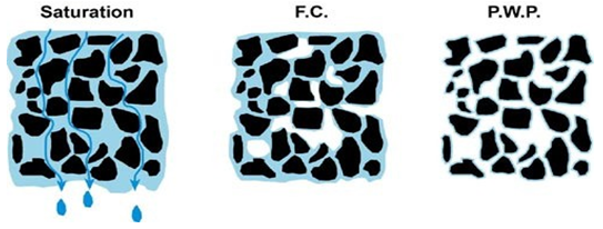
Fig. 24.1.Soil condition at Saturation, Field Capacity and Permanent wilting point.
(Source: www.terragis.bees.unsw.edu.au: accessed on May 30, 2013)

Table 24.1. soil water characteristics for various soil textures*
(Source: Eisenhuer, et al. 2008)
Although plants are theoretically able to obtain water from the soil whenever water contents exceed PWP, the actual rate at which they transpire decreases as stomata close in response to declining soil water contents. Fig. 24.2 indicate that soil moisture stress coefficient (Ks) remains almost unity for soil water content reductions between Fc and θt indicate that water is more readily available. However, as the moisture content decrease below θtsoil moisture stress coefficient decreases below unity and causes decreases in the crop transpiration (ET) at the same rate. Therefore, irrigations are generally scheduled to maintain soil water contents above θt. The water content between θFc&θt is called Readily Available Water (RAW). The concept of maximum allowable deficiency (MAD), is also used to determine the amount of water that can be used without adversely affecting the plant. The MAD is defined as:
![]() (24.2)
(24.2)
The value of MAD depends on soil and crop generally assumed a constant, but should be optimised based on local conditions.

Fig. 24.2.Soil moisture stress as a function of TAW.
(Source: Allen et al.1998)
24.2Soil Water Potential
The driving force for water flow in the soil-plant-atmosphere-continuum (SPAC) is the difference in water potential. Water flows from high to low potential.Soil water potential (Ψt) is an indicator or measure of amount of work needed to be done to displace a unit quantity of water from a given reference point. The water potential (ψ) can be expressed as the potential energy per unit mass, volume or weight.
Units of Water Potential
Mass basis : Joules/kg
Volume basis: Pascal
Weight basis : Meters or mm
The three major components of soil water potential are gravitational potential (Ψg), matric potential (Ψm), and osmotic potential (Ψo). The soil water potential (Ψt) then is
Ψt = Ψp(m) + Ψz +Ψo (24.3)
Where,
Ψp(m) = Pressure or (matric) potential
Ψz = gravitational potential
Ψo = osmotic potential
24.2.1 Gravitational Potential (Ψz)
Gravitational potential energy at a point Z above a reference point can be expressed as
![]() (24.4)
(24.4)
Where, Pw = density of water
V = Volume of water, cm3
g = Acceleration due to gravity
M = Mass of water
Gravitational potential energy per unit mass of water is the gravitational constant multiplied by the distance of the reference position and can be expressed as
Ψz / unit mass of water ![]() (24.5)
(24.5)
If the unit quantity of weight is used then the gravitational potential can be related to a distance. In other words, it is a vertical distance from an arbitrary reference elevation to the point of question.
![]() (24.6)
(24.6)
Example 24.1:
Given: Two points is a soil. Each point is located a specified distance above a reference elevation. Point A is 150mm above the reference and point B is 100 mm below reference.
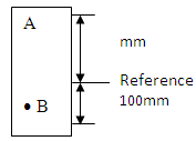
Find: - The Ψz at each point
- Difference in Ψz (Δ Ψz) between the two points.
Solution:
= 150 – (-100) = 250 mm
24.2.2 Pressure Potential (Ψp)
Pressure potential, under field conditions, applies mostly to saturated soil. For weight basis, it is the vertical distance from a point in question to tree water surface. The hydrostatic pressure of water with reference to atmospheric pressure can be expressed as:
Pressure (P) = ρwgh (24.7)
The potential energy of the water isPdv, where dv is the infinitesimal volume of water. The pressure potential on volume, weight and mass basis can be expressed as
![]() (24.8)
(24.8)
![]() (24.9)
(24.9)
![]() (24.10)
(24.10)
The pressure potential also known as the submergence potential, is an expression of the +ve pressure exerted on a point by the overburden pressure. It is measured by piezometer. Ψp is always be positive and to be zero if the water table below the point is question. In the example 24.1, if water table is reference and point B lies 100 mm below the water table then
Ψp (A) = 0 Ψp (B) 100mm
If
Ψp> 0 then +ve number and Ψm = 0
Ψm> 0 then –ve number and Ψp = 0
24.2.3 Metric Potential (Ψm)
It is the negative pressure potential related to the adsorptive forces of the soil matrix. Considering an infinitesimal volume dv of water, with pressure deficit, P, the metric potential will be Pdv. The pressure potential on volume, weight and mass basis can be expressed as
Metric potential per unit volume ![]() (24.11)
(24.11)
Metric potential per unit mass ![]() (24.12)
(24.12)
Metric potential per unit weight ![]() (24.13)
(24.13)
On weight basis Ψm is the vertical distance between a point in the soil and the water level of manometer connected to this point.
24.2.4 Osmotic Potential (Ψo)
Osmotic potential exists when soil water is having dissolved solids or salts. The osmotic potential affects the water uptake by plants. The osmotic potential is nearly zero where rainfall is significant and irrigation water is nearly free of salts, i.e., the concentration of salts in the soil is generally low. The osmotic potential has no effect on the flow of water through the soil profile.
24.3 Soil Moisture Measurement Methods
Measurement of soil-water is very important for many studies related to water management including irrigation scheduling, but it is not a simple process. Several methods have been proposed and each method has its own advantages and disadvantages. Some of the methods most commonly used are discussed below:
24.3.1 Direct Methods
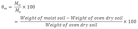
24.3.1.1 Gravimetric Method
The gravimetric method is the standard, direct measurement of soil water by which all indirect methods are calibrated. This method involves collecting soil sample from the field using auger,and determining its moist and dry weights. The moist weight is determined byweighing the soil sample (Ms) as it is at the time of sampling, and the dry weight is obtained after drying the soil sample in an oven at 105°C for 24 hours. The weight loss represents the soil water (Mw).
![]() (24.14)
(24.14)
24.3.1.2 Volumetric Method
The volumetric water content is defined as the volume of water present in agiven volume (usually 1 m3) of dry soil. This method involves collecting soil sample from the field using core samplerof known volume from representative depths in the root zone and then determining itsmoist and dry weights using the similar process as in case of gravimetric water content method. The difference in wet and dry mass of soil represent amount of water in the sample. The volumetric wetness can then be calculated as follows:
![]() (24.15)
(24.15)
To calculate the volume water content from gravimetric water content, we need toknow the bulk density ρbof dried soil and is calculated as follows:
![]() (24.16)
(24.16)
Depth of water (mm) per unit depth of soil (ds) = Θv X ds = Θm X ρb X ds (24.17)
24.3.2 Indirect Methods
24.3.2.1 Electrical Resistance Blocks
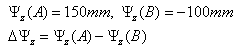
Electrical resistance blocks consist of two electrodes enclosed in a block of porous material. The block is often made of gypsum, and is referred to as gypsum blocks. The electrodes are connected to insulated lead wires that extend upward to the soil surface.Gypsum blocks or electrical resistance blocks, with two electrodes, are placed at a desired soil depth and allowed to equilibrate (Fig. 24.3). Resistance blocks work on the principle that water conducts electricity. When properly installed, the water suction of the porous block is in equilibrium with the soil-water suction of the surrounding soil.Electrical resistance of the block is measured by a meter. Electrical resistance of the soil decreases with increase in water content, i.e., low resistance (400 – 600 ohms) at field capacity and high resistance (50,000 to 75,000 ohms) at wilting point. Soil water content is obtained with calibration curve, for the same block, of electrical resistance against known soil water content.
Fig. 24.3. Measurement of soil moisture by Resistance blocks.
(Source: http://www.angrau.ac.in/media/7380/agro201.pdf : accessed on May 30, 2013)
24.3.2.2 Neutron Scattering Technique
The neutron scattering method is an efficient and reliable technique for monitoring soil moisture in the field.The neutron moisture meter consists of two main components (Fig. 24.4) viz., a probeand scaler. A probe contains a source of fast neutrons either mixture of americium and beryllium or mixture ofradium and beryllium, whereas scaler monitors the flux of slow or thermalized neutrons, which is proportional to soil water content.When the probe inserted in the access tube at desired depth, the fast neutronsare emitted radially into the soil. These fast neutrons thermalized when collide with hydrogennuclei (namely protons).Sphere of influence is spherical in shape, and rages in size from 10 cm in wet soil to 25 cm or more in dry soil. The slowed or thermalized neutrons when pass through detector, create a small electrical pulses which are amplified and counted byscaler over a specified interval of time. Scaler displays either counts or volumetric water content.
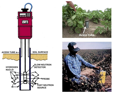
Fig. 24.4.Measurement of soil moisture by neutron probe.
(Source: http://www.angrau.ac.in/media/7380/agro201.pdf : accessed on May 30, 2013)
24.3.2.3 Time Domain Reflectrometery (TDR)
Time domain reflectometry (TDR) is a relatively new method for the measurement of soil water content and electrical conductivity. Fig. 24.5 shows TDR probe for soil moisture measurement. TDR measures the transit time of an electrical signal along metallic probes. This time is closely related to the dielectric constant of the material surrounding the probe. The dielectric constant of liquid water is much higher (about 80) than soil solids (2 to 5). Thus, the time measured can be related to soil water content. The TDR method offers a number of advantages over other soil water measurement methods. These include
- Better accuracy to within 1 or 2% volumetric water content;
- Soil-specific calibration is not needed in many case;
- TDR has excellent spatial and temporal resolution; and
- Measurements are simple to obtain, andthe method is capable of providing continuous measurements throughautomation and multiplexing.
- Allows to measure moisture content near soil surface thus is compliments neutrons probe, which not measure surface water contents well.
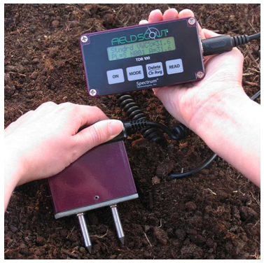
Fig. 24.5. TDR probe for soil water measurement.
(Source:http://www.enviromonitors.co.uk/catalogue/tdr100-soilmoisture accessed on August 28, 2013)
24.3.2.4Tensiometer
Tensiometer measures the matric potential, which indicate the tenacity with which water is held by the soil (Fig. 24.6). To obtain soil water content from tensiometer, soil moisture characteristics curve (a relationship between soil water content and matric potential) is required. Tensiometer consists of a porous ceramiccup which is connected through a tube to a vacuum gauge (or manometer). The tensiometer is filled with water before inserting in the soil. When the Tensiometer is initially placed in the soil, the watercontained in the tensiometer is generally at atmospheric pressure (essentially, 0 barstension). Soil water, being generally at sub- atmospheric pressure, exercises a suction, which draws out a certain amount of water from the rigid and air tighttensiometer thus causing negative pressureinside the tube. This is indicated by a vacuum gauge or manometer. Under field conditions the sensitivity of mosttensiometers is a maximal tension of about 0.85 bars or 85 kPa.Tensiometers are suited well for use in sandy soil since large part of plant available water is held at tension less than 1 atmosphere. One the other hand, they are not well suited for fine textured soil since only part of plant available water is held at tension less than 1 bar.
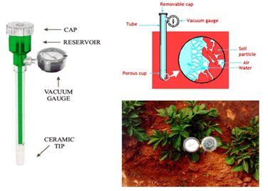
Fig. 24.6.Measurement of soil moisture tension by tensiometer.
(Source: http://www.angrau.ac.in/media/7380/agro201.pdf: accessed on May 30, 2013)
Example 24.2:
A moist soil sample collected from agricultural field weighs 120 g. When it is dried the soil weighs 100 g. density of soil is 2.4 g/cm3. Calculate the gravimetric moisture content and volumetric moisture content of the soil sample. Depth of water present in soil as the depth of soil is 75 cm.
Solution:
Water mass = weight of moist sample- weight of dried sample= 120 – 100 = 20 g.
We know,
Therefore, ![]() = 20 %
= 20 %
And, ![]()
Depth of water (mm) per unit depth of soil (ds) = Θv X ds = 0.48 X 75 = 36 cm (Ans)
References
Allen, R. G., Pereira, L. S., Raes, D., and Smith M. (1998).CropnEvapotranspiration: Guidelines for computing crop water requirements.Irrigation and Drainage Paper No. 56. Rome: FAO.
Eisenhauer, D., Martin, D. and Hoffman, G.(2008).Irrigation Principles and Management.BiosystemEngg Dept., Univ. of Nebraska, Lincoln.
Michael, A.M. (2008). Irrigation Theory and Practice.Vikas Publishing House PvtLtd. New Delhi.
Murty, V.V.N. (2002).Land and Water Management Engineering (Fourth Edition).Kalyani Publisher, New Delhi.
Internet References
http://www.angrau.ac.in/media/7380/agro201.pdf
http://gilley.tamu.edu/BAEN464/Handout%20Items/Cuenca%20Book%20Chapter%203%20Soil%20Physics.pdf
http://www.fao.org/docrep/r4082e/r4082e03.htm
http://ilri.org/InfoServ/Webpub/fulldocs/IWMI_IPMSmodules/Module_3.pdf
ftp://ftp.wcc.nrcs.usda.gov/wntsc/waterMgt/irrigation/NEH15/ch1.pdf
Suggested Reading
http://www.fao.org/docrep/r4082e/r4082e03.htm
ftp://ftp.wcc.nrcs.usda.gov/wntsc/waterMgt/irrigation/NEH15/ch1.pdf
http://storm.okstate.edu/bae3313/Lecture/8)%20soilwaterplant%20relationships/soil-water-plant%20relationships.pdf
http://www.academia.edu/705434/Comparison_of_techniques_for_measuring_the_water_content_of_soil_and_other_porous_media
http://www.angrau.ac.in/media/7380/agro201.pdf
Last modified: Thursday, 6 March 2014, 11:14 AM