Site pages
Current course
Participants
General
Module 1:Water Resources Utilization& Irrigati...
Module 2:Measurement of Irrigation Water
Module 3: Irrigation Water Conveyance Systems
Module 4: Land Grading Survey and Design
Module 5: Soil –Water – Atmosphere Plants Intera...
Module 6: Surface Irrigation Methods
Module 7: Pressurized Irrigation
Module 8: Economic Evaluation of Irrigation Projec...
19 April - 25 April
26 April - 2 May
LESSON 43 Description of Drip System Components and their Selection-II
This lesson presents the important components of the control head of the drip irrigation system viz. Fertigation units and filtration system. Fertigation unit is required for the application of nutrients along with water to the crop root zone which is the main concept of drip irrigation system and responsible for achieving the maximum productivity along with the minimum losses of chemicals and fertilisers. Filtration unit is required to provide filtered water in to the system to prevent the small openings or narrow pathways of the emitting devices for improving the performance of the system.
43.1 Fertigation
Application of fertilizers and chemicals along with water through drip or sprinkler system is known as fertigation or chemigation. Fertilisers that are water soluble can be effectively and efficiently applied through drip irrigation system. Compared to the conventional methods of fertilizer and water application, fertigation offers several benefits such as reduced labour, equipment and energy costs and higher fertilizer use efficiency. The success of drip irrigation, to a good degree, is due to the improved supply of nutrients along with water at the desired location. Hence the use of appropriate fertigation equipment is necessary. Plant protection chemicals can also be applied effectively using the same equipments.
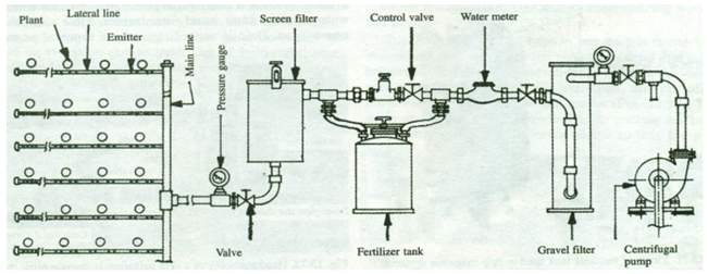
Fig. 43.1. The arrangement of different components of drip irrigation system with fertigation and filtration units. (Source: Michael, 2010, pp.641)
Fig. 43.1 illustrates the control head assembly in overall layout of different components of drip irrigation system. The control head assembly of a drip irrigation system consists of fertigation equipment, filters, control valves and other accessories.
43.1.1 Selection and Types of Fertigation Unit
The requirement of fertilizer application in terms of quantity and type of fertilisers to be injected, concentration and time schedule should be considered in deciding the types of fertigation equipment in drip irrigation system. Some of the fertilizers are not suitable for application through drip systems, because of volatalization of gaseous ammonia, low water solubility and problems with the chemical quality of irrigation water. Therefore, fertilizers that need to be used and the type of fertigation equipment should be decided with an understanding of the chemical composition of the fertilizers to be used. Nitrogen is relatively problem free. The type of fertigation equipments that is chosen also depends on the crop grown and the farm management system.
43.1.2 Equipment and Methods for Fertilizer Injection
Fertilizers and other agrochemicals such as herbicides and pesticides into the drip irrigation system can be injected by:
i) By pass pressure tank
ii) Venturi system and
iii) Direct injection system
i) By Pass Pressure Tank
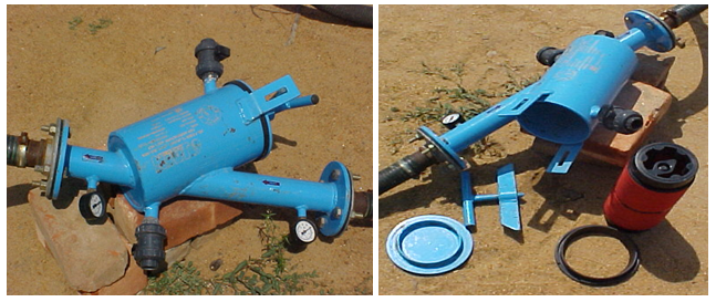
This method consists of a tank into which the water soluble dry or liquid fertilizers are stored. The tank is connected to the main irrigation line by means of a bypass so that some of the irrigation water flows through the tank and dilutes the fertilizer solution. This by pass flow is brought about by a pressure gradient between the entrance and exit of the tank. This pressure difference between the entrance pipe to the fertiliser tank and the exit pipe is created by a gate valve, pressure regulator or permanent constriction in the line or by a control valve. Fig. 43.2 shows by- pass pressure tank.
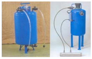
Fig. 43.2. By- pass pressure tank. (Source: Tiwari, 2009, pp. 591)
ii) Venturi Injector
In case of the venturi injector, there is a constriction in the main water flow pipe that increases the water flow velocity thereby causing a pressure differential (vacuum) sufficient to suck fertilizer solution from an open reservoir/tank into the main water flow. The rate of injection can be regulated by means of valves. This is a simple and relatively inexpensive method of fertilizer application. Fig. 43.2 shows venturi injector.
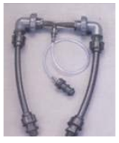
Fig. 43.3. Venturi Injector. (Source: Tiwari, 2009, pp.591)
iii) Direct Injection System
Direct injection system employs a pump to inject fertilizer solution into the irrigation line. The type of pump used depends on the power source. The pump may be driven by an internal combustion engine, an electric motor or hydraulic pressure. The electric pump can be automatically controlled and is thus the most convenient to use. However its use is constrained by the limited availability of electrical power. The use of a hydraulic pump, driven by the water pressure of the irrigation system, eliminates this limitation. The injection rate of fertilizer solution is proportional to the flow of water in the system. A high degree of control over the injection rate is possible, no serious head loss occurs and operating cost is low.
43.2 Filtration System
Irrigation water quality is defined by its physical, chemical and biological characteristics. The narrow water passageways in drippers and micro-emitters are particularly sensitive to irrigation water quality. Poor water quality if allowed to enter the system clogs the emitters. Narrow pathways in the emitters coupled with low velocity of water aggravate the clogging. The clogging of the emitters is the most difficult problem that can encounter in the operation of the drip irrigation system, if not dealt properly. The clogging that blocks the water pathways in the emitters fully or partially reduces the discharge in varying degrees affecting the performance of the system in terms of precise application of water to the soil root zone and uniformity in application. Thus the clogging tends to loss of precious water and fertilisers and reduction in crop yield. Keeping contaminants entering from the system or forming within the system is the best preventive measure against the clogging. Hence the appropriate filtration system is the important component of the drip irrigation system.
The relative clogging of drip emitters depends on the size of particulars suspended in irrigation water. Table 43.1 provides the relative clogging potential of drip irrigation systems by water contaminants.
Table 43.1. Relative clogging potential of drip irrigation systems by water contaminants
|
Water characteristic |
Minor |
Moderate |
Severe |
|
Suspended solids (ppm) |
<50 |
50-100 |
>100 |
|
pH |
<7.0 |
7.0-8.0 |
>8.0 |
|
Total dissolved solids (ppm) |
<500 |
500-2000 |
>2000 |
|
Manganese (ppm) |
<0.1 |
0.1-1.5 |
>1.5 |
|
Iron (ppm) |
<0.2 |
0.2-1.5 |
>1.5 |
|
Hydrogen sulphide (ppm) |
<0.2 |
0.2-2.0 |
>2.0 |
|
Bacteria population (per ml) |
<10,000 |
10,000-50,000 |
>50,000 |
(Source: Bucks and Nakayama, 1900)
Filtration system should be able to filter or process all the water entering in to the system and should be able to remove
i) Suspended solid mineral particles
ii) Organic matter
iii) Live zooplankton
The particles many times smaller than the size of the water pathways in the emitter should be removed by the filtration system as in the process of time many particles can group together to block the water pathways. In general following five types of the filters are used in combination or standalone depending on the need.
-
Screen filter
-
Disc filter
-
Media filter
-
Hydrocyclone filter
-
Settling ponds
43.2.1 Screen (Strainer) Filters
Screen filter and disc filters (described in the subsequent section) are considered as the primary filter. One of these two filters is essential even water is free of all kinds of impurities. Screen filter has five main parts. These are: Casing or basket, filter element or cylindrical screen, rubber seal or gasket, inlet and outlet. Screens are usually made from stainless steel or nylon. Screen filters are designated by filtration degree, filtration surface area and filtration ratio. Filtration degree is designated in microns or mesh number. The filtration degree in microns indicates the diameter of the biggest ball-shaped particle that can pass between the screen wires. The mesh number indicates the number of openings per inch with a standard wire size. The two concepts i.e. hole size and the mesh number are not fully inter-convertible. Perforation width may differ in two screens with the same mesh number due to different wire thickness. Conversion from one system to another is done by rule of thumb: mesh number microns15,000. The screen mesh number and corresponding hole size for typical wire size is given in Table 43.2.
Table 43.2. The screen mesh number and corresponding hole size for typical wire size
|
Screen mesh number |
Hole size |
|
|
mm |
inch |
|
|
4 |
4.76 |
0.1874 |
|
10 |
2.00 |
0.0787 |
|
20 |
0.84 |
0.0331 |
|
40 |
0.42 |
0.0165 |
|
80 |
0.172 |
0.0068 |
|
140 |
0.105 |
0.0041 |
|
200 |
0.074 |
0.0029 |
(Karmelli and Keller, 1974)
The screen mesh should be such so that the screen retains all particles larger than one sixth the size of smallest passage (openings) in the drip system (British Columbia, Ministry of Agriculture, 1982). The required filter screen area can be estimated by an empirical ratio between the open area in the filter basket (the sum of the holes) and the cross sectional area of the exit pipe of the filter. This ratio should be at least 2.0. When using fine screens, the wire mesh occupies approximately one half of the area. Figure 43.4 shows (a) Screen filter (b) Elements of a screen filter.
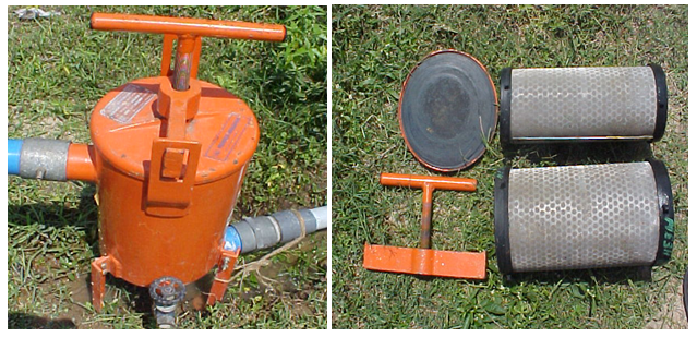
(a) (b)
Fig. 43.4. (a) Screen filter, (b) Elements of a screen filter. (Image source: Report of the task force on Micro-Irrigation, Ministry of Agriculture, Department of Agriculture & Cooperation, Govt. of India, New Delhi,Jan, 2004)
In screen filters any impurities or dirt materials accumulated on the surface of the screen for long time causes increase in, the head loss across the filter. This, if not monitored properly, reduces the operating head available at the emitter and discharge affecting the performance of the emitters adversely. The pressure difference between the filter inlet and outlet is, therefore, monitored to know excessive dirt accumulation on the screen. The pressure difference between inlet and outlet should not exceed 0.5 bar (5m). Filters then need to be flushed manually i.e. by pulling out the filter element and cleaning it by washing or automatically which takes place during the filter operation either continuously, on a time schedule or whenever the pressure loss across the filter reaches a certain level. Extreme care needs to be taken to prevent the dirt from bypassing the filter in to the system during the cleaning.
43.2.2 Disc Filters
Disc filters are suitable for filtration of water containing mixed, inorganic and organic impurities such as algae. The casing is made of metal or plastic materials (Fig. 43.6). The filtering element is stack of grooved rings, tightened firmly by a screw on cap or by a spring that is compressed by a water-piston. The sizes of the grooves determine the of filtration grade. Water is filtered as it flows from the perimeter into the stack inner space through the grooves. The intersections of the grooves provide in-depth filtering. Coarse particles are trapped on the external surface of the stack whereas finer particles and organic debris stick to the inner grooves. Disc filters have a higher dirt-retention capacity than screen filters. Disk filters are available in different flow rates varying from 4 to 30 m3h-1. Figure 43.5 shows (a) Disc filter (b) Elements of disc filter. The disc filters can also be manually or automatically washed. In case of manual washing, the stack of discs is loosened and water at high pressure is sprayed on the grooves of the disc to remove dirt accumlated in the grooves.
(a) (b)
Fig. 43.5. (a) Disc filter, (b) Elements of a disc filter.
43.2.3 Media Filter
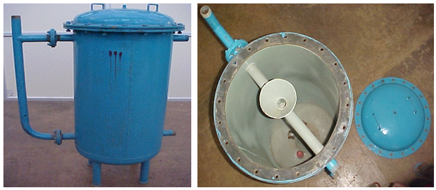
Sand or media filters consist of layered beds of graduated sand and/or fine gravel placed inside the cylindrical pressurized tank. As the water passes through the tank, the gravel and sand carry out the filtration process. Media filters are used to remove high organic load from open water bodies or reclaimed water and heavy loads of very fine sand. Normally tanks or media containers (0.5 m – 1.25 m in diameter) are made of epoxy-coated carbon steel, stainless steel or fiberglass. The filtering media is 1.5 mm – 4 mm size basalt, gravel, crushed granite particles or fine silica sand.The filter material be as coarse textured as possible but fine enough to retain all particles larger than one sixth the size of the smallest passage way in the drip system. Filter materials should be large enough, Such that it should not be removed by filter cleaning or backwashing process. The organic impurities adhere to the surface of the media particles. The accumulated dirt should be back-flushed routinely in order to eliminate excessive head losses. American Societies of Agricultural Engineers recommend pressure drop across the media filter not to exceed 70 kPa. Fig. 43.6 shows (a) Media filter (b) Elements of media filter. Screen filter/disc filter needs to be used invariably downstream of the media filter to pick up any particles which might escape the media filter in filtering or backwashing process.
(a) (b)
Fig. 43.6. (a) Media filter (b) Elements of a media filter.
43.2.4 Hydro cyclone Filter or Centrifugal Sand Separators
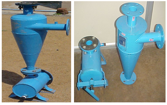
High loads of sand or other solid particles if present in irrigation water needs to be removed before getting to the main filtration system. The media screen and disc filters cannot perform the filtering operations effectively in this case. The traditional practice of separation of heavy sand load is based on sedimentation of solid sand particles by slowing –down water flow in to the settling tanks or basins and then re-pump the treated water into the irrigation system. In centrifugal (vortex) sand separators, the water is introduced tangentially at the top of a cone creating a circular motion resulting in to centrifugal force which throws heavy suspended particles against the wall. The sand particles thrown against the container wall by the centrifugal force settle down and accumulate in a collecting chamber at the bottom (Fig.43.7). The collector is washed out manually or automatically. Clean water exits through an outlet at the top of the separator. A suitable sand separator can be designed for any flow rate ranging from 3m3h-1-300 m3h-1 without excessive head-losses. Such filters are effective for primary filtration of river or canal waters. These filters are capable of removing to up 98% of the sand particles which would be contained by a 200 mesh screen.
(a) (b)
Fig. 43.7. (a) Centrifugal sand separator, (b) Working pattern.
43.2.5 Settling Basins
Settling basins, ponds or reservoirs are used to remove large volumes of sand and silts from the irrigation water. However the water stored in open water bodies may develop algae growth and wind blown contaminants in the ponds may cause more filtration problems than before. In addition to this, water needs to be re-pumped in to the system.
43.3 Selection of Emitters
Emitter is a device used to dissipate water pressure and to discharge water at a constant flow rate at many points on a lateral as uniformly as possible. The objective of the water passageways of emitters is to maximize pressure dissipation to approach atmospheric pressure in the emitter outlet. The commonly used drippers are online pressure compensating or online non-pressure compensating, in-line dripper, adjustable discharge type drippers, vortex type drippers and micro tubing of 1 to 4 mm diameter. These are manufactured from poly- propylene or LLDPE.
43.3.1 Online Pressure Compensating Drippers: A pressure compensating type dripper supplies water uniformly on long rows and on uneven slopes within prescribed variation in pressure. These emitters consist of high quality flexible rubber diaphragm or disc inside the emitter that changes shape according to operating pressure and delivers uniform discharge (Fig. 43.8). These are most suitable on sloping lands and difficult topographic terrains.
Fig. 43.8. Online Pressure Compensating Drippers.
(Source: Report of the task force on Micro-Irrigation, Ministry of Agriculture, Department of Agriculture & Cooperation, Govt. of India, New Delhi, Jan, 2004)
43.3.2 Online Non-Pressure Compensating Drippers: In such type of drippers discharge tends to vary with operating pressure. They have simple thread type, labyrinth type, zigzag path, vortex type flow path or have float type arrangement to dissipate energy. However they are less expensive and available in affordable prices compared to pressure compensating emitters. Different types of on line non-pressure compensating types of drippers are shown in Fig. 43.9.
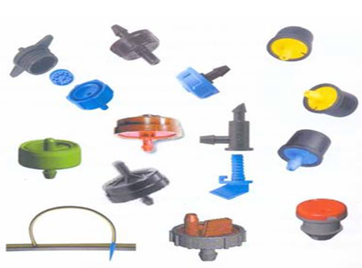
Fig.43.9. Online non-pressure compensating drippers. (Image source: Report of the task force on Micro-Irrigation, Ministry of Agriculture, Department of Agriculture & Cooperation, Govt. of India, New Delhi,Jan, 2004)
43.3.3 Point Source Emitters
Point source emitters dissipate water pressure through a long narrow path and a vortex chamber or a small orifice before discharging into the air (Fig.42 .10). The emitters can take a predetermined water pressure at its inlet and reduce it to almost zero as the water exits. The typical flow rates range from 2 to 8 lph. The point source emitters can be on line or inline or integrated (Fig. 42.11), pressure compensating or non pressure compensating; surface or subsurface.
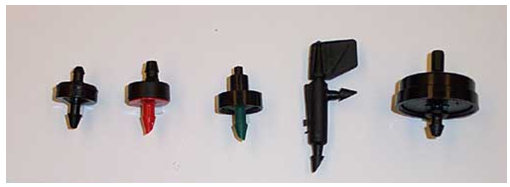
Fig. 43.10. Point source emitter.
(Source: Report of the task force on Micro-Irrigation, Ministry of Agriculture, Department of Agriculture & Cooperation, Govt. of India, New Delhi, Jan,2004).
43.3.4 Line Source Emitter
Line source emitters consist of the drip tubing having perforations continuously along its length. The pressure is dissipated as the water discharges through a large number of very small pores or perforations in the lateral pipe wall, instead of discharging through emitting devices. Twin wall type is more commonly used. In this case there is inner tubing which is known as main tubing. The outer tubing is known as auxiliary tubing. Both the tubings are concentric twin wall type. The main tubing of the pipe serves as the lateral. Inside this tubing major portion of water flows under relatively high pressure. A small number of widely spaced holes connect the main tubing to the auxiliary tubing. The auxiliary tubing is provided with five to ten types as many holes per unit of length as the main tubing. The water discharges through the numerous holes of the auxiliary tubing to the outside. The inner and outer holes are of the same size. The inner holes act as pressure dissipaters and outer holes distribute the water. The flow rate is typically expressed in Lh-1meter length. Drip lines are either buried below the ground or laid on the surface. Burial of the drip line is preferred to avoid degradation from heat and ultraviolet rays and displacement from strong winds. However, some specialized equipment to install and extract the thin drip distribution line is required.
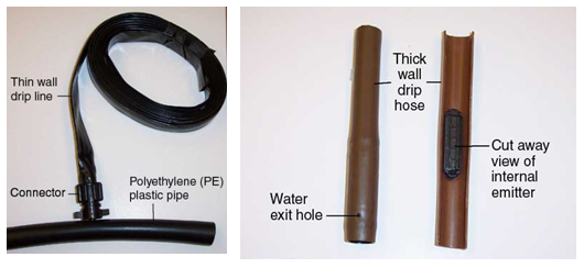
Fig. 42.11. Drip line with integrated emitters.
(Source: http://fvtchort.wikispaces.com/Soils+Group+1)
43.4 The Flow Characteristics of the Emitters
The flow characteristics of the emitters is presented by the following equation
q = kHx
where
q = emitter discharge (Lh-1)
k = a constant of proportionality that characterise each emitter
H = working pressure head at the emitter (m)
x = the emitter discharge exponent that is characterised by the flow regime.
The lower the value of x, the less discharge will be affected by pressure variations. In fully turbulent flow x=0.5 and in laminar flow x=1.0. Non compensating orifice and nozzle emitters are always fully turbulent with x = 0.5 and x =0.0 for fully compensating emitters. However the exponents of long path emitters may range anywhere between 0.5 and 1.0.
References
British Columbia Ministry of Agriculture. (1982). Water treatment guidelines for trickle irrigation. Engineering Reference Information R512.000: 2.
Michael, A. M., (2010). Irrigation Theory and Practice, Vikas Publishing House Pvt. Ltd, Delhi, India: 641.
Tiwari. K. N. (2009) Pressurized Irrigation, Precision Farming Development Centre Publication No. PFDC/ IIT KGP/2/2009: 25.
Suggested Readings
James, L G. (1988). Principles of Farm Irrigation System Design, John Wiley and Sons, Inc., New York: 288-297.
Howell, T.A., Stevenson D.S., Aljibury, F.K., Giltin, H.M., Wu, I.P., Warrick, A.W. and Raats, P.A.C. (1980). Design and operation of trickle (Drip) system (In design and operation of Farm Irrigation system, Chapter 16; edited by Jensen, M.E.) ASAE Monograph 3, ASAE Michigan USA.
Last modified: Friday, 14 March 2014, 5:30 AM