Site pages
Current course
Participants
General
Module 1. Micro-irrigation
Module 2. Drip Irrigation System Design and Instal...
Module 3. Sprinkler Irrigation
Module 4. Fertigation System
Module 5. Quality Assurance & Economic Analysis
Module 6. Automation of Micro Irrigation System
Module 7. Greenhouse/Polyhouse Technology
12 April - 18 April
19 April - 25 April
26 April - 2 May
Lesson 10. Installation and Maintenance Guidelines
10.1 Micro-irrigation System Installation
The main items in the installation of drip irrigation system include installation of the head assembly (control head), comprising the pumping set, non-return valve, water meter, filters, fertilization equipment, and flow control, air release and pressure release valves. The next step for installation include connecting mains, sub mains, laying of drip tape or lateralsand connecting drippers.
10.1.1 Installation of Filters and Fertigation Equipment
A hard base made of concrete is constructed for installation filters and other head control units as per the size. Care should be takento use of minimum number of accessories like elbows and reducersso as to avoid huge head loss. The filter size should be in accordance with the capacity of the system. The delivery pipe of the pump should be connected directly to the hydrocyclone or the media filter followed by the fertilizer equipment and the screen filter then connected with the main pipe.Once the sand/screen filters are installed in the correct position the arrangement for back washing of filter is one of essential requirement.
In pressurized irrigation system the fertilizer injection unit is located between the sand filter (if required) and the screen filter. The general recommendation is that the fertilizer solution should pass through at least two 90-degree turns to ensure adequate time for thorough mixing so as to remove precipitate with the help of the screen filter. It is must that fertigation unit is installed at the upstream end of the screen filter so as to filter theundisolved matter present in the fertilizer solution.
10.1.2 Installation of Mains and Sub-mains
Except for fully portable system, both the mains and sub mains are installed underground at a minimum depth of about 0.5m such that they are unaffected by cultivation or by movement of heavy harvesting machinery. Even for systems, which have portable laterals that are removed at the end of each season, it is common practice to install permanent by underground mains and sub mains. Generally sub mains run across the direction of the rows.
The United States Soil Conservation Service has recommended the following minimum cover of earth over for various pipe sizes (Hamish, 1977):
|
Pipe size |
Depth of earth cover |
|
1.2 to 6 cm diameter |
45 cm |
|
6 to 10 cm diameter |
60 cm |
|
Over 60 cm diameter |
75 cm |
It is important to clean mud and other impurities deposited in the pipe before fitting of mains, and sub-mains and gate valves. A ball valve is provided at the inlet end of the sub-main. After the ball valve, air release valve is provided on drip tape and sub-main. A flush valve facing the slope of the sub-mains is provided at the end of each sub-main to facilitate sub-main flushing.
10.1.3 Laying of laterals
Once the gromate take offs are fixed on the sub-mains, lateral/polytube laying is done as per the design. For this, holes are drilled on the sub-main, according to the gromate take off (GTO) i.e., 11.9 mm dia drill for 8 mm ID GTO and 16.5 mm drill for 13 mm ID GTO. Then gromates are fixed in it and then take off are fixed. Lateral is fixed to one end of the take off. Lateral placement is done according to row distance, with sufficient shrinking allowance and extra lateral is provided and the end. The drippers are punched on the laterals as per the crop requirement.
Generally laterals are laid on the ground surface. Usually laterals are placed along contours on sloping field. Burying laterals underground might be necessary or at least have some advantages for some installations. Where this is done, the emission devices should be kept above ground level. The downstream end of the lateral can be closed by simply folding back the pipe and closing it with a ring of larger diameter pipe, known as end plug. This can be easily slipped for flushing.
10.1.4 Punching of Laterals andFixing of Emitters
Punching of laterals should start from sub-main end. Water should be allowed to flow through lateral so as to get bulging in pipe which makes easy punching. The dripper position is fixed as per the crop spacing and requirement. All the drippers should follow straight line. Drippers are fixed on laterals as per the arrows marked and it should be towards the sub-mains.While fixing the dripper, push it inside the lateral and pull it slightly. The end of lateral should be closed with end cap.
10.2 Operation of Drip Irrigation System
The proper operation of a drip irrigation system involves the following steps:
i) Acquiring complete information and instructions from the designer and dealer.
ii) Determining when and how long to irrigate.
iii) Checking the water meter readings and recording the values.
iv) Accurately setting the hydraulic metering valve.
v) Operating the head valve to begin irrigation.
vi) Checking the system along all components for proper operation, beginning with pressure readings at the header.
vii) Checking the emitters discharge, at least on a random basis.
viii) Setting and operating the chemical and fertilizer injection equipment (US Soil Cons. Service, 1984).
10.3 Maintenance of Micro Iirrigation System
Periodic preventive maintenance is required for successful operation of micro irrigation system. The emitter functioning, wetting pattern and leakage of pipes, valves, and fittings should be checked regularly. The placement of emitters should be ascertained. If the placement is disturbed, put the emitter in proper location. Leakage through filter gaskets in the lids, flushing valves & fittings etc. are monitored regularly.
10.3.1 Filter Cleaning
Filter is the heart of a drip system and its failure will lead to clogging of the entire system. Pressure differential across the filter is the correct indication of the timing of cleaning of the filter(Tiwari, 2009).
i) Hydro cyclone filter: Hydro cyclone filter should be installed before sand and screen filter. Hydro cyclone filter requires least maintenance. For cleaning the dirt inside of under flow chamber open back washing valve daily. Flush the chamber by opening flush valve/cap for thorough cleaning.
ii) Sand filter: The sand filter should be backwashed every day for five minutes to remove the silt and other dirt accumulated during the previous day’s irrigation. Once in a week, while back washing, the backwash water should be allowed to pass through the lid instead of the backwash valves. The sand in the filter bed is stirred upto the filter candles without damaging them. Thedirt accumulated deep inside the sand bed should be allowed to go with the water through the lid. The need of back washing can be detected by monitoring the pressure drop across the filter. When the pressure drops has increased to a pre-determined level, the filter should be back-flushed. ASAE recommends that this pressure drop should not exceed 70 kPa.
iii) Screen filter: Flushing at scheduled daily interval is necessary to maintain screen filter. It is recommended to flush screen filter, if pressure drops more than 0.5 kg cm-2 (5 m water column). Before the start of drip irrigation system, the flush valve on the filter lid should be kept opened so that the dirt and silt is flushed out. The filter element is taken out from the filter and it is cleaned in flowing water. The rubber seals are taken out from both the sides and precaution should be taken while replacing the rubber seals, otherwise they may get damaged.
10.3.2 Maintenance of Fertigation Equipment
Initially theventury injector should be operated with clean water for 10 to 15 minutes after fertilizer application. It will prevent clogging of suction port of ventury from clogging. It is important to note that equipment is resistant to acid attack. The lid of the fertilizer tank should be fully tightened while in operation. In order to check leaks between the body and bell housing in fertigation pump, clean the seal seating and put back the seal or change and keep the position of bell housing at upright.
10.3.3 Sub-main and Lateral / Bi-wall Flushing
Sometimes silt escapes through the filters and settles in sub mains and laterals. Also some algae and bacteria lead to the formation of slimes/pastes in the pipe and laterals. To remove these formations the sub mains should be flushed by opening the flush valves. The lateral lines should be flushed by removing the end caps. By flushing, even the traces of accumulated salts will also be removed. The flushing is stopped once the water going out is appearcleaned.
10.3.4 Chemical Treatment
Clogging or plugging of emitters/orifices of bi-wall is due to precipitation and accumulation of certain dissolved salts like carbonates, bi-carbonates, iron, calcium and manganese salts. The clogging is also due to the presence of microorganisms and the related iron and sulphur slimes due to algae and bacteria.The clogging or plugging is usually removed by chemical treatment. Chemical treatments commonly used in microirrigation system include addition of chloride and/or acid to the water supply. The frequency of chemical treatment is decided on the degree of clogging and quality of water. As a general rule, acid treatment is performed once in ten days and chlorine treatment once in fifteen days.
i) Acid treatment: Hydrochloric acid is injected into the micro irrigation system at the rate suggested in the water analysis report. The acid treatment is performed till a pH of 4 is observed at the end of pipe. After achieving a pH of 4 the system is shutofffor 24 hours. Next day the system is flushed by opening the flush valve and lateral end caps.
ii) Chlorine treatment: Chlorine treatment in the form of bleaching powder is performed to inhibit the growth of microorganism like algae and bacteria. The bleaching powder is dissolved in water and this solution is injected intothe system for about 30 minutes. Then the system is shut off for 24 h. After that the lateral end caps and flush valves are opened to flush out the water with impurities. The recommended chlorine dosage of 0.5 to 1.0 ppm concentration is applied continuously or 20 ppm for 20 minutes at the end of each irrigation cycle for algae while for slimes, 1.0 ppm free residual chlorine is maintained at the end of each laterals. For iron precipitation, 0.64 times the Fe++ content are used to maintain 1.0 ppm free residual chlorine at the end of each lateral.Efficiency of chlorine injection is related to pH of the water to be treated. More chlorine is required for a high pH of water. The rate of injection of liquid chlorine or acid depends on the system flow rate and can be determined by using the following equation
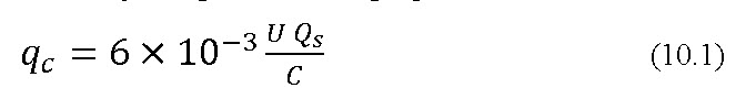
where
\[{{\rm{q}}_{\rm{c}}}\]= Rate of injection of the chemical into the system, L h-1
U= Desired concentration of chemical in irrigation water, ppm
\[{{\rm{Q}}_{\rm{s}}}\]= Supply flow rate, Lmin-1
\[{\rm{C}}\]= Concentration of chemical in the solution to be injected, per cent
References:
Hamish, F. (1977). Main Line Installation, in Drip/Trickle Irrigation No.5(2), 2Pub. International Drip Irrigation Asso., P.O. Box 288, Bloomington, California-92316 (714) 877-4405, p. 12.
United States Department of Agriculture, Soil Conservation Service (1984), Trickle Irrigation. US Dept. of Agriculture, Soil Conservation Service, National Engineering Handbook Chapter 15, Section 15. U.S.D.A., S.C.S., Washington, D.C., pp.129.
Tiwari, K. N. (2009). Pressurized Irrigation, Precision Farming Development Center Publication No. PFDC/ IIT KGP/2/2009 Agricultural & Food Engineering Department, IIT Kharagpur.
Suggested Reading:
Michael, A. M., (2010). Irrigation Theory and Practice, Vikas Publishing House Pvt. Ltd, Delhi, India,: 643-645.
Howell T.A, Stevenson D.S, Aljibury F.K., Giltin H.M, Wu I.P, Warrick A.W. and Raats P.A.C (1980) Design and Operation of Trickle (Drip) System (In Design and Operation of Farm Irrigation System, Chapter 16; edited by Jensen, M.E.) ASAE Monograph 3, ASAE Michigan USA.
Last modified: Saturday, 18 January 2014, 6:34 AM