Site pages
Current course
Participants
General
Module 1: Introduction and Concepts of Remote Sensing
Module 2: Sensors, Platforms and Tracking System
Module 3: Fundamentals of Aerial Photography
Module 4: Digital Image Processing
Module 5: Microwave and Radar System
Module 6: Geographic Information Systems (GIS)
Module 7: Data Models and Structures
Module 8: Map Projections and Datum
Module 9: Operations on Spatial Data
Module 10: Fundamentals of Global Positioning System
Lesson 4 Sensors Characteristics
4.1 Remote Sensing Sensors
Sensor is an electronic circuit which can record the electromagnetic radiation incident upon it. A sensor is a device comprising of optical component or system and a detector with electronic circuit. It senses a variation in input energy to produce a variation in another or same form of energy. All sensors employed on earth observation platforms use electromagnetic radiation to observe terrain features. Various types of sensor are employed based on requirements and purpose. Remote sensing sensors measure radiance of objects under study in a given wavelength. They comprise of several components such as-
System to receive radiation from the pixel and a telescope (objective),
Calibration source and spectrometer,
Amplifier and recording system,
The sensor thus represents an imaging radiometer, often called scanner, essentially consisting of a radiometer supported by a system of image acquisition, pixel by pixel.
4.2 Classification of Remote Sensing Sensors
Remote sensors can be broadly classified as passive sensors and active sensors. Sensors which sense natural radiation, either emitted or reflected from the earth are called passive sensors. This process is known as passive remote sensing (Fig. 4.1.). It is also possible to produce electromagnetic radiation of a specific wavelength or band of wavelengths as a part of the sensor system. The interaction of this radiation with the target could then be studied by sensing the scattered radiation from the targets. Such sensors, which produce their own electromagnetic radiation, are called active sensors. This process of remote sensing is active remote sensing (Fig. 4.2.). Since the technology for developing microwave sensors is quite different from that of optical infrared (OIR) sensors, from the standpoint of understanding the design and realization of the sensors, it is convenient to classify the sensors (both passive and active) as those operating in the OIR region and those operating in the microwave region. The OIR and microwave sensors could be either imaging or non imaging sensors. Imaging sensors give a two dimensional spatial distribution of the emitted or reflected intensity of the electromagnetic radiation (as in a photographic camera), while the non imaging sensors measure the intensity of radiation, within the field of view, and in some cases as a function of distance along the line of sight of the instrument (for example, vertical temperature profiling radiometer -VTPR). Fig. 4.3. shows the remote sensors classification.
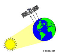
Fig. 4.1. Passive remote sensing.
(Sources: www.nrcan.gc.ca/earth-sciences/geography-boundary/ remote-sensing/fundamentals/1212, August 17, 2012.)
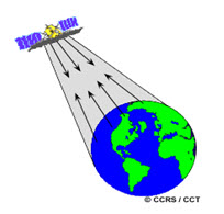
Fig. 4.2. Active remote sensing.
(Sources: www.nrcan.gc.ca/earth-sciences/geography-boundary/ remote-sensing/fundamentals/1212, August 17, 2012.)
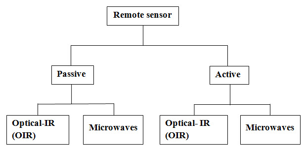
Fig. 4.3. Remote sensing sensors classification. (Source: Joseph, 2005)
The sensors may be broadly be divided classified based on their working principles and recording medicines.
1) Photographic camera
2) The vidicon using detecting media as television camera
3) The optical scanner
4) Microwave radiometer
5) Microwave radar
4.3 Sensors Parameters and Resolution
The information collected by the remote sensors is meant to identify and map various earth surface objects. Therefore, we may say that the performance of the sensor is evaluated based on its classification as well as its mapping accuracy requirements. It is reasonable to assume that this will depend on the instruments ability to detect small differences in the emittance/ reflectance of the earth’s surface in a number of spectral bands for as small an object as possible and as often as possible.
Then the important question is what is the optimum set of specifications for a remote sensor? Unfortunately, there is no unique answer, since the choice of the optimum parameters depends on the theme under study. Even if one identifies an ideal set of parameters, the realization of a combination of these parametric values (i.e., spatial resolution, number of spectral bands, spectral bandwidth, signal to noise ratio, etc.) in a sensor system is a complex problem due to the strong interrelationship among these parameters and requirements of the sensor. We may consider the sensor parameters under four domains: (1) spatial (2) spectral (3) radiometric (4) temporal.
Resolution
In remote sensing, a given area of earth surface is observed by the sensor with each measurement corresponding to an elemental area on the surface over number of spectral bands. Then one can think of resolution. Resolution is defined as a measure of sensor ability to distinguish between signals. All remote sensing information is resolution dependent. The various parameters which characterize theses different kinds of sensor systems are described by resolution. The quality of remote sensing data depends on its spatial, spectral, radiometric and temporal resolution.
Spatial resolution refers to the size of the smallest object that can be detected in an image. The basic unit in an image is called a pixel. One-meter spatial resolution means each pixel image represents an area of one square meter in the ground. Smaller an area represented by one pixel, higher the spatial resolution of the image. Fig. 4.4. explains the details of spatial resolution. For example spatial resolution of Landsat 7, ETM+ sensor 30 m for band 1-5, 7; 60 m for band 6, and 15 m for band 8. It means that one image pixel corresponds to 30 m x 30 m area in the terrain for band 1 – 5; 60 m x 60 m area in the terrain for band 6 and 15 m x 15 m area in the terrain for band 8.
![]()
Fig. 4.4. Pixel resolution. (Source:www.satimagingcorp.com/characterization-of-satellite-remote -sensing-systems.html)
Spectral resolution refers to the number of bands and the wavelength width of each band. A band is a narrow portion of the electromagnetic spectrum. Shorter wavelength widths can be distinguished in higher spectral resolution images. Multi-spectral imagery can measure several wavelength bands such as visible green or NIR. Landsat, Quickbird and Spot satellites use multi-spectral sensors. Hyperspectral imagery measures energy in narrower and more numerous bands than multi-spectral imagery. The narrow bands of hyperspectral imagery are more sensitive to variations in energy wavelengths and therefore have a greater potential to detect crop stress than multi-spectral imagery. Multi-spectral and hyperspectral imagery are used together to provide a more complete picture of crop conditions.
Table 4.1 Specification of LISS-III and LISS-IV sensors of IRS-P6
|
|
LISS-IV |
LISS-III |
|
|
Spatial Resolution |
Band 2 (green) |
5.8 m |
23.5 m |
|
Radiometric resolution, |
all Bands |
7 bit |
7 bit |
|
Spectral Coverage |
Band 2 (green) |
520-590 nm |
520-590 nm |
(Source: www.euromap.de/docs/doc_005.html)
Radiometric resolution refers to the sensitivity of a remote sensor to variations in the reflectance levels. The higher the radiometric resolution of a remote sensor, the more sensitive it is to detecting small differences in reflectance values. Higher radiometric resolution allows a remote sensor to provide a more precise picture of a specific portion of the electromagnetic spectrum. Thus it refers to quantization levels of DV values in an image. Radiometric resolution is expressed in bits such 8-bit, 9-bit and 10-bit image has radiometric resolution 256(=28), 512(=29) and 1024(=210) respectively. Resourcesat-2 has LISS-III and LISS-IV sensor with 10-bit radiometric resolution and AWiFS sensor with 12-bit radiometric resolution.
Temporal resolution refers to how often a remote sensing platform can provide coverage of an area. Geo-stationary satellites can provide continuous sensing while normal orbiting satellites can only provide data each time they pass over an area. Remote sensing taken from cameras mounted on airplanes is often used to provide data for applications requiring more frequent sensing. Cloud cover can interfere with the data from a scheduled remotely sensed data system. Remote sensors located in fields or attached to agricultural equipment can provide the most frequent temporal resolution.
Temporal resolution or the revisit time period is 5 days for LISS-IV and 24 days for LISS-III of IRS-P6, 16 days of Landsat ETM+, 2-3 days (latitude) of SPOT 5.
Keywords: Remote sensor, Active sensor, Passive sensor, Resolution, Radiometer, Optical scanner, Pixel.
Reference
Joseph, G., 2005, Fundamentals of remote sensing, Universities Press (India) Private Limited, pp. 129-130.
www.nrcan.gc.ca/earth-sciences/geography-boundary/ remote-sensing/fundamentals/1212
www.satimagingcorp.com/characterization-of-satellite-remote-sensing-systems.html
www.euromap.de/docs/doc_005.html; August 14, 2012.
Suggested Readings
Bhatta, B., 2008, Remote sensing and GIS, Oxford University Press, New Delhi, pp. 49-56.
www.crisp.nus.edu.sg/~research/tutorial/image.htm; August 14, 2012.
www.eotec.com/images/IRS_-_Current_and_Future_-_Web.pdf
calval.cr.usgs.gov/documents/IRSP6.pdf
eoedu.belspo.be/en/satellites/irs.htm; August 14, 2012.
www.aprsaf.org/data/aprsaf13_data/2_4_Disast_work_sentil_ISRO_1515day1.pdf
Last modified: Tuesday, 21 January 2014, 5:44 AM