Site pages
Current course
Participants
General
Module 1. Perspective on Soil and Water Conservation
Module 2. Pre-requisites for Soil and Water Conse...
Module 3. Design of Permanent Gully Control Struct...
Module 4. Water Storage Structures
Module 5. Trenching and Diversion Structures
Module 6. Cost Estimation
5 April - 11 April
12 April - 18 April
19 April - 25 April
26 April - 2 May
Lesson 8. Runoff Measurement using Flumes
8.1 Flumes
A flume is a stabilized channel section for measuring the flow. They are less inclined than weirs which make them well suited for runoff measurement. They require a very low head loss for operation. Examples of flumes are Parshall flume, H-flume, cut-throat flume, long-throated flume and venturing flume. They can be a “flat-bottom” type. In the case of a flat-bottom flume, the shape of the side walls creates a contraction of the flow of liquid (ex. Cut-throat flume). They can also combine vertical and side contractions (ex. Parshall flume).
Flumes work according to the venturi principle by reducing the flow area, velocity increases and water depth changes. A flume usually has three sections: a converging section, throat section and diverging section. Sizes vary according to the type and shape of flume. For practical purposes, to determine the absolute flow of a flume, the calibration curves supplied by the manufacturer should be used.
Advantages
Minimal drop in pressure.
Enables measurement in a large range of flow.
The flow-rate in flumes is usually high enough to prevent sedimentation; they are therefore self-cleaning.
Provides a reliable measurement in free flow and submerged flow conditions.
Disadvantages
Installation is usually expensive.
Installation requires extremely careful work.
Requires a secure watertight base.
Flow at the entrance must be evenly distributed, with little turbulence, to produce accurate measurements.
8.2 Parshall Flume
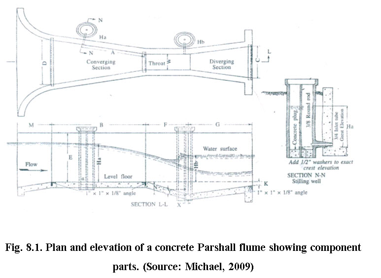
Parshall flumes are devices for the measurement of flow of water in open channels when depth of flow is less i.e., head drop is very small, the volume of flow is less and channel bed slope is less. Fig. 8.1 shows Parshall flume. The flume consists a converging section with a level floor and walls converges towards the throat section, a throat section with a downward sloping floor and parallel walls, and a diverging section with an upward sloping floor and diverging walls towards the outlet. The size of flume is determined by the width of its throat. The size ranges from 7.5 cm to several m in throat width.
Parshall flumes are available in various sizes. Care must be taken while constructing the flumes exactly in accordance with structural dimensions.
On the basis of the throat width, Parshall flumes have been classified into three main groups.
(i) Very small - 25.4 mm to 76.2 mm.
(ii) Small 152.40 mm to 2438.4 mm.
(iii) Large 3048 mm to 15240 mm.
Standard dimensions of Parshall flumes with discharge values are presented in Table 8.1 and 8.2, respectively. Discharge through the flume can occur under either free or submerged flow condition. Flow is submerged when the down-stream water elevation retards the rate of discharge. To determine discharge through the flume under free flow condition, head is measured at upstream section (Ha). However, downstream head (Hb) is also measured for submerged flow condition. Free flow condition prevails if the submergence ratio (Hb/Ha) remains within 0.5, 0.6 and 0.7 for width of throat varying from 2.5 to 7.5 cm, 1.5 to 22.5 cm and 3.0 to 24.0 cm, respectively.
Table 8.1. Dimensions and capacities of Parshall flume of various sizes (Letter, refer Fig. 8.1) (Source: Michael, 2009)
|
Throat width |
A |
B |
C |
D |
E |
F |
G |
K |
N |
X |
Y |
Free-flow capacity |
|
|
cm |
cm |
cm |
cm |
cm |
cm |
cm |
cm |
cm |
cm |
cm |
cm |
Minimum, litres/ second |
Maximum, litres / second |
|
7.5 |
31 |
46 |
18 |
26 |
46 |
15 |
30.5 |
2.5 |
5.7 |
2.5 |
3.8 |
0.85 |
28.4 |
|
15 |
41.4 |
61 |
39 |
39.7 |
61 |
30.5 |
61 |
7.6 |
12 |
5.1 |
7.6 |
1.4 |
110.8 |
|
23 |
58.8 |
86 |
38 |
57.5 |
76 |
30.5 |
45.5 |
7.6 |
12 |
5.1 |
7.6 |
2.5 |
253 |
|
30 |
91.5 |
134 |
61 |
84.5 |
92 |
61 |
91.5 |
7.6 |
23 |
5.1 |
7.6 |
3.13 |
456.6 |
Table 8.2. Free flow discharge values for Parshall Flume.
|
|
Discharge, litres-per second |
|||
|
Head |
Throat width |
|||
|
cm |
7.5 cm |
15 cm |
23 cm |
30 cm |
|
3 |
0.8 |
1.4 |
2.6 |
3.1 |
|
4 |
1.2 |
2.3 |
4 |
4.5 |
|
5 |
1.7 |
3.3 |
5.5 |
7 |
|
6 |
2.3 |
4.4 |
7.2 |
9.6 |
|
7 |
2.7 |
5.4 |
8.5 |
11.4 |
|
8 |
3.4 |
7.2 |
11.1 |
14.4 |
|
9 |
4.3 |
8.5 |
13.5 |
17.7 |
|
10 |
5 |
10.2 |
15.9 |
21.1 |
|
11 |
5.8 |
11.6 |
18.1 |
23.8 |
|
12 |
6.7 |
13.5 |
21.1 |
27.5 |
|
13 |
7.5 |
15 |
23.3 |
31 |
|
14 |
8.5 |
17.3 |
26.7 |
35 |
|
15 |
9.4 |
19.2 |
29.5 |
38.7 |
|
16 |
10.4 |
21.2 |
32.5 |
42.7 |
|
17 |
11.4 |
23.2 |
35.6 |
46.6 |
|
18 |
12.4 |
25.3 |
39 |
51.2 |
|
19 |
13.6 |
27.8 |
42.5 |
55 |
|
20 |
14.3 |
30 |
45.8 |
59.7 |
|
21 |
15.8 |
32.7 |
49.3 |
64.7 |
|
22 |
17.1 |
35.2 |
53.3 |
69.8 |
|
23 |
18.2 |
37.7 |
56.8 |
74 |
|
24 |
19.4 |
40.1 |
60.5 |
79 |
|
25 |
20.7 |
42.7 |
64.5 |
84.1 |
|
26 |
22 |
45.7 |
69.3 |
89 |
|
27 |
23.3 |
48.1 |
72.4 |
94.3 |
|
28 |
24.8 |
51.5 |
76.7 |
100 |
|
29 |
26 |
54 |
80.7 |
105.1 |
|
30 |
27.5 |
57.3 |
85.2 |
111 |
(Source: Michael, 2009)
8.2.1 Flow Measurement
Generally, Parshall flumes are calibrated empirically in laboratory conditions before installing in the field. However in case of free flow conditions, the discharge is measured by the following formula:
Where, Q is the discharge, C, n is the flume coefficients which vary with the size of the flume, and H is the measuring head.
Table 8.3 gives a set of standard values for the C, n for different dimensions (these co-efficient are in fps units so the calculated discharge would be in ft3/s and head has to be in ft,)
Table 8.3. Value of C and n for different throat widths
|
Throat width |
Coefficient (C) |
Exponent (n) |
|
1 in |
0.338 |
1.55 |
|
2 in |
0.676 |
1.55 |
|
3 in |
0.992 |
1.55 |
|
6 in |
2.06 |
1.58 |
|
9 in |
3.07 |
1.53 |
|
1 ft |
3.95 |
1.55 |
|
2 ft |
8.00 |
1.55 |
|
3 ft |
12.00 |
1.57 |
|
4 ft |
16.00 |
1.58 |
|
5 ft |
20.00 |
1.59 |
|
6 ft |
24.00 |
1.59 |
|
7 ft |
28.00 |
1.60 |
|
8 ft |
32.00 |
1.61 |
|
10 ft |
39.38 |
1.60 |
|
12 ft |
46.75 |
1.60 |
|
15 ft |
57.81 |
1.60 |
|
20 ft |
76.25 |
1.60 |
|
25 ft |
94.69 |
1.60 |
|
30 ft |
113.13 |
1.60 |
|
40 ft |
150.00 |
1.60 |
|
50 ft |
186.88 |
1.60 |
(source:http://www.usbr.gov/pmts/hydraulics_lab/pubs/wmm/chap08_10.html, accessed on 16/7/2013)
In the above figure, Ha is upstream head and Hb is downstream head.
Advantages:
i) This instrument is effective when the total head drop is small.
ii) Its operation is independent of approaching velocity.
iii) Being a self-cleaning device, it is not affected by sand or silt deposition.
8.2.2 Installation of Parshall flume
The Parshall flumes are installed considering the upstream condition, flume crest and downstream channel
Upstream conditions: Upstream conditions should promote laminar flow conditions at the flume inlet. Channel turns, tees, elevation drops or other obstructions should be avoided. The upstream channel slope should not allow excessive velocity at the flume. A slope of almost flat, to 3% maximum, for very small flumes, and 2% maximum for larger flumes is the ideal slope value. A 1:4 sloping ramp upstream should be provided for flumes that must be installed above the channel floor.
Crest of the flume: The crest of the flume (the floor of the converging section where depth measurements are made) must be level both longitudinally & transversely.
Downstream channel: The downstream channel should not permit submerged flow conditions to occur. Long, narrow, flat or undersized channels can result in a backwater effect at the flume and should be avoided. A large fall or steep slope immediately downstream of the metering station can eliminate the possibility of submerged flow conditions.
8.3 H Flumes
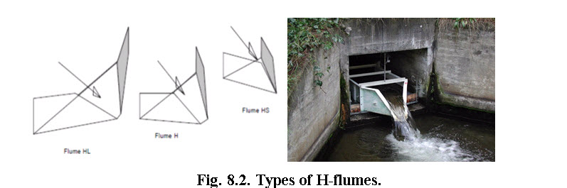
H flumes were designed in the mid-1930s by the USDA Agricultural Research Service. H-flumes (Fig.8.2) are devices to guide the natural flow to converge through V-type cross section. In H flume, the high flows pass at wide opening whereas at low flow the opening is reduced to maintain the sensitivity of flow measurement. The H-flumes measure highly varying flow (as high as 100 times to the low flow) accurately.
(Source: http://www.ceaeq.gouv.qc.ca/documents/publications/guides_ech.htm accessed on 16/7/2013)
Based on the capacity of flumes, there are three categories of H flumes: Hs, H and HL, all of which have the same shape, but differ in size and angles. Design parameters and dimensions for different flumes are given in Tables 8.4 and 8.5, respectively.
1. HS-Flumes: Of this ‘small’ category H-flume, the flow depth is restricted to 30cm and is capable to measure flow ranging between 0.005 to 23 l/s.
2. H-Flumes: Of this ‘normal’ category H-flume. In this case the maximum flow depth are 1.4m and the is able to measure flow ranging from 0.01 l/s to 2400 l/s.
3. HL-flumes: This is largest H-flume among the three categories. Though in this case also, the maximum flow depth is 1.4m, the HL-flume is wider than the normal H-flume and hence the accuracy is lesser. The use of this type of flume is only recommended if the anticipated discharge exceeds the capacity of the normal H-flume. The HL-flume is able to handle flow rate as high as 3300 l/s.
Table 8.4. Design parameters of different type of H-flume
|
Type |
W/H |
L/H |
T/H |
|
HS |
1.90 |
1.35 |
0.1 |
|
H |
1.05 |
1.50 |
0.05 |
|
HL |
3.20 |
1.50 |
0.2 |
(Source:http://www.hydrology.uga.edu/rasmussen/class/4300/weirs.html, accessed on October 12, 2013)
Table 8.5. Dimension of different type of H-flume
|
Type |
Flume Dimensions (feet)1 |
|||
|
Height |
Width |
Length |
Spout |
|
|
H |
W |
L |
T |
|
|
H |
0.5 |
0.95 |
0.68 |
0.05 |
|
0.75 |
1.43 |
1.01 |
0.08 |
|
|
1.00 |
1.90 |
1.35 |
0.10 |
|
|
1.5 |
2.85 |
2.03 |
0.15 |
|
|
2.00 |
3.80 |
2.70 |
0.20 |
|
|
2.50 |
4.75 |
3.38 |
0.25 |
|
|
3.00 |
5.70 |
4.05 |
0.30 |
|
|
4.50 |
8.55 |
6.08 |
0.45 |
|
|
HS |
0.40 |
0.42 |
0.60 |
0.02 |
|
0.60 |
0.63 |
0.90 |
0.03 |
|
|
HL |
4.00 |
12.80 |
6.00 |
0.80 |
(Source:http://www.hydrology.uga.edu/rasmussen/class/4300/weirs.html, accessed on October 12, 2013)
8.3.1 Description
An H flume is the result of a combination of the physical and mechanical characteristics of a weir and flume. Because of its shape, it resembles a triangular weir more than a flume. It consists of two sections: approach section shaped by converging sides, and the control section consisting an opening that is the result of shape of the converging sides.
8.3.2 Operating Principle
An H flume operates according to the Venturi principle. Due to lateral restrictions, the flume restricts the flow area, causing the water level upstream from the throat to rise. The flow can be obtained by simply measuring the water depth, because this depth varies proportionally with flow.
This type of flumes can be used under both free and submerged flow conditions. Their use in free flow conditions is strongly recommended. In a free flow condition, a flow measurement can be obtained using only one measuring point, but in submerged flow conditions, the depth downstream from the throat section must also be measured.
8.3.3 Applications
An H flume was developed to measure the flow of irrigation water from small catchment areas and surface water. It is also used to measure the flow of irrigation water, slow-flowing watercourses and water in sewer systems.
The geometry and operating principle of an H flume make it a very useful tool for measuring the flow of water that contains solids.
It is easy to manufacture, relatively inexpensive and is suitable for temporary measurement systems.
8.3.4 Installation of H-flumes
When a flume is installed, it is important to ensure that the flume’s physical characteristics correspond to recommended dimensions. When flumes are installed, the approach boxes should, whenever possible, be placed below the natural ground surface. Where the watershed or plot slope is small and the flow is dispersed, gutters may be provided to collect the runoff at the bottom of the slope and channel it into the approach box. Metal flumes should be fixed to the concrete approach. The concrete cut-off wall should extend below the concrete approach at the upstream face of the flume to provide substantial support and to prevent seepage below the flume. The flume floor must be level. If silting is a problem, a 1 in 8 sloping false floor can be set to concentrate low flows and thereby reduce silting.
Reference
Michael, A.M. (2009). Irrigation Theory and Practice, Vikas Publication House Pvt. Ltd., Noida, India.
Ministère Du Développement Durable, De L’Environnement Et Des Parcs Du Québec. (2007). Sampling Guide for Environmental Analysis: Booklet 7 – Flow Measurement Methods in Open Channels, Centre d’expertise en analyseenvironnementale du Québec.
Skogerboe, G.V. Hyatt, M. L. England, J. D. and Johnson, J.R. (1966). Measuring Water with Parshall Flumes, Reports in Utah Water Research Laboratory,Paper 83.
Internet references
http://digitalcommons.usu.edu/water_rep/83 accessed on 16/7/2013
http://www.ceaeq.gouv.qc.ca/documents/publications/guides_ech.htm accessed on 16/7/2013
http://www.fao.org/docrep/T0848E/t0848e-09.htm accessed on 6/7/2013
http://www.globalw.com/support/ParshallInstall.html accessed on 6/7/2013
http://www.usbr.gov/pmts/hydraulics_lab/pubs/wmm/chap08_10.html, accessed on 16/7/2013
http://www.hydrology.uga.edu/rasmussen/class/4300/weirs.html, accessed on October 12, 2013.
Suggested Readings
Das, G. (2000). Hydrology and Soil Conservation Engineering, Prentice Hall of India Private Ltd., New Delhi, India.
Hudson, N. W. (1993). Field Measurement of Soil Erosion and Runoff, FAO Corporate Document Repository, FAO, Roam
Schwab, G.O. Fangmeier, D.D. Elliot, W.T. Frevert, R.K. (1993). Soil and Water Conservation Engineering, John Wiley & Sons, New York, United States.
Last modified: Monday, 27 January 2014, 11:34 AM