Site pages
Current course
Participants
General
Module 1. Perspective on Soil and Water Conservation
Module 2. Pre-requisites for Soil and Water Conse...
Module 3. Design of Permanent Gully Control Struct...
Module 4. Water Storage Structures
Module 5. Trenching and Diversion Structures
Module 6. Cost Estimation
5 April - 11 April
12 April - 18 April
19 April - 25 April
26 April - 2 May
Lesson 16. Drop Spillway Design
16.1 Introduction
In the previous lecture, design considerations of permanent gully control structures are discussed. These include hydrologic design, hydraulic design and structural design. In additions, details about drop spillway are also discussed. In this lecture our focus would be on hydrologic and hydraulic design of drop spillway. The hydraulic structures are failed mainly due to their insufficient hydraulic capacity and lack of provision for dissipating the energy of falling water into the structure. That is why, design of these structures is done considering not only to have sufficient discharge handling capacity, but also for dissipating the kinetic energy of falling discharge within the structure in such a manner and to limit that will protect the structure and downstream channel from the erosion.
16.2 Principle of Hydrologic Design
It involves the estimation of design runoff rate and flood volume, which the structures is expected handle safely. This is done by computing the peak runoff rate for 25 to 30 years return period. Runoff rate is calculated using the Rational method:
Where, Qpeak is the peak runoff rate, m3/s; C is the runoff coefficient; I is the rainfall intensity (cm/h) for the duration equal to time of concentration of watershed and for a given recurrence interval; A is the watershed area, ha.
Hydraulic design consists of determining the dimension of different components of the structure, on the basis of expected maximum runoff rate determined using the Rational method. The dimension of the structure should have sufficient capacity and also provision for dissipating the kinetic energy of discharge falling towards downstream face of the structure. This phenomenon helps in controlling the channel erosion below the structure.
16.2.1 Design of Drop Spillway
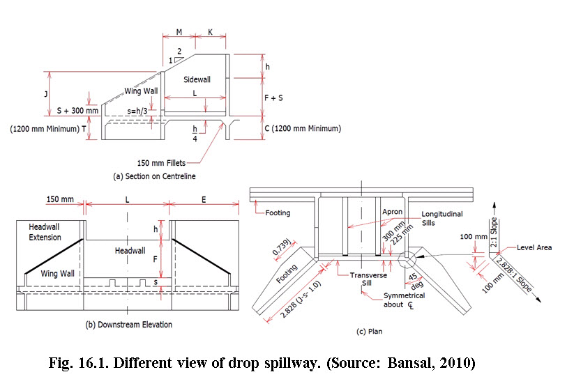
The hydraulic design of drop structures includes three major steps namely, inlet design, conduit (mostly rectangular weir) and outlet design. The different views of drop spillway, e.g., plan, side view and downstream elevation are presented in Fig. 16.1.
16.2.2 Computation of Length and Depth of Weir
Straight drop spillway consists of straight type inlet that is why its name became as straight drop spillway. This type of inlet is most suitable for wide and shallow gullies to handle small to medium flows.
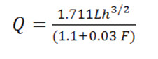
To calculate the inflow capacity of straight drop spillway, the following weir formula may be used:
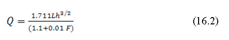
Where, Q is the maximum discharge capacity of the weir (cumec); L is the length of weir (m); h is the total depth of weir (m); and F is the net drop from top of transverse sill to crest (m).
The site condition best describes the values of L and h. The values of L,h and F can be taken from standard table which are given in Table 1. The ratio between depth of flow (h) and net drop (F) influences the scouring. Higher ratio increases the scouring tendency and lower values of this ratio will result into lower system performance. So for most economical design, this ratio is recommended to be lower than 0.5 and should not be more than 0.75 in any case.
Table 16.1. Discharge capacities for straight drop spillways with net drop, F = 2 m. multiply by correction factor for other drops (discharge capacity Q, cumec)
|
h, m |
Length of weir (L, m) |
|||||||||||||||||||
|
|
1 |
1.5 |
2 |
2.5 |
3 |
3.5 |
4 |
4.5 |
5 |
5.5 |
6 |
|||||||||
|
0.4 |
0.39 |
0.5 |
0.77 |
0.97 |
1.16 |
1.35 |
1.55 |
1.74 |
1.93 |
2.13 |
2.32 |
|||||||||
|
0.5 |
0.54 |
0.81 |
1.08 |
1.35 |
1.62 |
1.89 |
2.16 |
2.43 |
2.7 |
2.97 |
3.24 |
|||||||||
|
0.6 |
0.71 |
1.07 |
1.42 |
1.78 |
2.13 |
2.49 |
2.84 |
3.2 |
3.55 |
3.91 |
4.26 |
|||||||||
|
0.7 |
0.89 |
1.34 |
1.79 |
2.24 |
2.68 |
3.13 |
3.58 |
4.03 |
4.47 |
4.92 |
5.37 |
|||||||||
|
0.8 |
1.09 |
1.64 |
2.19 |
2.73 |
3.28 |
3.83 |
4.37 |
4.92 |
5.47 |
6.01 |
6.56 |
|||||||||
|
0.9 |
1.3 |
1.96 |
2.61 |
3.26 |
3.91 |
4.57 |
5.22 |
5.87 |
6.52 |
7.17 |
7.83 |
|||||||||
|
1 |
1.53 |
2.29 |
3.06 |
3.82 |
4.58 |
5.35 |
6.11 |
6.87 |
7.64 |
8.4 |
9.17 |
|||||||||
|
1.1 |
1.76 |
2.64 |
3.52 |
4.41 |
5.29 |
6.17 |
7.05 |
7.93 |
8.81 |
9.69 |
10.57 |
|||||||||
|
1.2 |
2.01 |
3.01 |
4.02 |
5.02 |
6.02 |
7.03 |
8.03 |
9.04 |
10.04 |
11.05 |
12.05 |
|||||||||
|
1.3 |
2.26 |
3.4 |
4.53 |
5.66 |
6.79 |
7.93 |
9.06 |
10.19 |
11.32 |
12.45 |
13.59 |
|||||||||
|
1.4 |
2.53 |
3.8 |
5.06 |
6.33 |
7.59 |
8.86 |
10.12 |
11.39 |
12.65 |
13.92 |
15.18 |
|||||||||
|
1.5 |
2.81 |
4.21 |
5.71 |
7.02 |
8.42 |
9.82 |
11.23 |
12.63 |
14.03 |
15.44 |
16.84 |
|||||||||
|
Correction factor for the other drops from 0.5 m to 3.0 m |
||||||||||||||||||||
|
Net Drop F (m) |
0.5 |
0.75 |
1.0 |
1.25 |
1.50 |
1.75 |
2.0 |
2.25 |
2.5 |
2.75 |
3.0 |
|||||||||
|
Correction factor |
1.114 |
1.112 |
1.009 |
1.007 |
1.004 |
1.002 |
1.000 |
0.989 |
0.996 |
0.993 |
0.99 |
|||||||||
(Source: Singh et al., 1981)
The ratio of L/h should not be less than 2 for rectangular weir. The dimension L, h and F are decided by the above mention procedure. Once these dimensions are finalized, the dimensions of other components of the drop spillway are calculated using the following guiding procedure.
16.2.3 Computation of Hydraulic Components
Height of longitudinal and end sill, HL= h/4 (16.3)
Height of transverse sill, S = h/3 (16.4)
Minimum length of head wall extension,
E (m) = (3h+0.6) or 1.5 F, whichever is greater. (16.5)
Length of stilling basin or length of apron,
![]()
Height of wing wall and side wall at junction,
![]()
Height of headwall extension (HE)
HE = F + S +h (16.8)
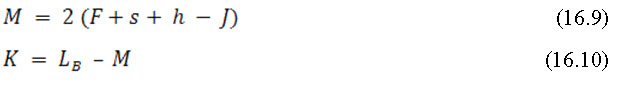
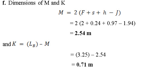
The components M and K, as shown inFig.16.1 (a) are calculated by the following equations
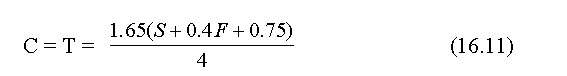
Depth of cutoff wall: The depth of cutoff wall (C) and toe wall (T) are considered to be same. It can be calculated using the following formula given by USDA,
Apron thickness: Varies from 0.2 to 0.3 m depending upon the depth of fall. Thickness of apron in plain concrete for different values of overfall F, can be determined from the Table 2.
Table 16.2. Apron thickness
|
Overfall, F (m) |
0.5- 0.75 |
1.0 – 1.25 |
1.5 – 1.75 |
2.0 – 2.25 |
2.5 – 3.0 |
|
Apron thickness (cm) |
20 |
25 |
25 |
30 |
30 |
(Source: Singh et al., 1981)
For masonry and gabion structures, these thickness may be increased by 1.5 and 2 times respectively.
Wall thickness: Top widths and base width of headwall, sidewall, wingwall and headwall extensions for different wall heights for masonry construction are given in Table 3.
Table 16.3. Drop spillways in stone and masonry
|
Description |
Headwall |
Sidewall |
Wingwall&Headwall Extension
Headwall extension |
|
Minimum top width (m) |
0.45 |
0.3 |
0.3 |
|
Height of headwall (H) |
Recommended base width |
||
|
0.5 |
0.45 |
0.3 |
0.3 |
|
1 |
0.67 |
0.55 |
0.4 |
|
1.5 |
1 |
0.82 |
0.6 |
|
2 |
1.33 |
1.1 |
0.8 |
|
2.5 |
1.67 |
1.37 |
1 |
|
3 |
2 |
1.65 |
1.2 |
|
3.5 |
- |
- |
1.4 |
|
4 |
- |
- |
1.6 |
|
4.5 |
- |
- |
1.8 |
(Source: Singh et al., 1981)
Example 16.1:
Design a drop structure which is to be constructed across the gully. The catchment area of the gully is 50 ha. The maximum rainfall intensity was recorded as 12 cm/h once in 50 - years return period, for the period equal to Tc. The drop of bed is 2 m. (Assume necessary data required).
Solution:
- Computation of peak discharge
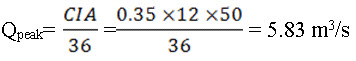
Assuming the value of runoff coefficient as 0.35. - Computation of combinations of L and h for the discharge Q as 5.83 m3/s: it is calculated using following equation.
The different values of ‘L’ are assumed and the values of ‘h’, h/F and L/h are computed, as shown in following table.
|
L (cm) |
3 |
3.5 |
4 |
4.5 |
5 |
|
h (cm) |
1.17 |
1.06 |
0.97 |
0.90 |
0.84 |
|
h/F |
0.56 |
0.53 |
0.49 |
0.45 |
0.42 |
|
L/h |
2.56 |
3.30 |
4.12 |
5.0 |
5.95 |
For selection of suitable combination of L and h, the value of h/F >0.5 is not suitable. Further, in all case, L/h ratio is greater than 2. Hence L ranges from 4.0 to 5.0 m, may be selected as suitable combinations. Let
Length of crest, (L) = 4.0 m
and corresponding to this L value, the h = 0.97 m
3. Computation of design of different hydraulic parts of the drop structure
a. Minimum length of head wall extension
E = 3h + 0.6 or 1.5 F whichever is greater
= 3 x 0.97 + 0.6 or 1.5 x 2
= 3.51 or 3.0 m
Between above two values of E, the higher value is 3.51 m, hence it is selected as the minimum length of head wall extension.
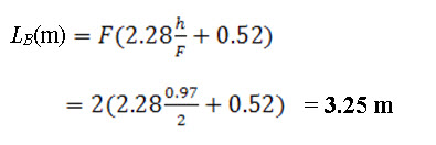
b. Length of apron: The length of apron and stilling basin (LB) are the same, which is computed by the following equation
c. Height of transverse sill
ht = h/3 = 0.97/3 = 0.32 m
d. Height of longitudinal sill
S= h/4 = 0.97/4 = 0.24 m
e. Height of wing wall and side wall at junction:
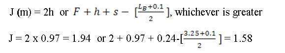
The values of J are obtained as 1.94 m and 1.58 m. Between them the higher value i.e., 1.94 m is selected as the height of wing wall and side wall at the junction point.
g. Cutoff wall and toe wall
C = T =
= (1.65 (0.24 + (0.4 x 2) + 0.75))/4
= 0.73 m
References
Das, G. (2000). Hydrology and Soil Conservation Engineering. EEE Publication. Prentice – Hall of India PVT. LTD. New Delhi.
Ojha, T.P., and Michael, A.M. (2006). Principles of Agricultural Engineering. Volume-II. Jain Brothers. New Delhi.
Suresh, R. (1993). Soil and Water Conservation Engineering. Standard Publishers and Distributors,New Delhi.
Internet References
Suggested Readings
Das, G. (2000). Hydrology and Soil Conservation Engineering. EEE Publication. Prentice – Hall of India PVT. LTD. New Delhi.
Michael, A.M. and Ojha, T. P. (2006). Principles of Agricultural Engineering.
Volume-II. Jain Brothers. New Delhi.
Suresh, R. (1993). Soil and Water Conservation Engineering. Standard Publishers and Distributors,New Delhi.
Last modified: Wednesday, 5 February 2014, 10:29 AM