Site pages
Current course
Participants
General
Module 1. Perspective on Soil and Water Conservation
Module 2. Pre-requisites for Soil and Water Conse...
Module 3. Design of Permanent Gully Control Struct...
Module 4. Water Storage Structures
Module 5. Trenching and Diversion Structures
Module 6. Cost Estimation
5 April - 11 April
12 April - 18 April
19 April - 25 April
26 April - 2 May
Lesson 22. Design of Chute Spillway
In the previous lecture, chute spillway and its components of chute spillway are discussed. In this lecture, design of SAF stilling basin and structural design of chute spillway is discussed.
22.1 Design Layout of Chute Spillway
The structural details of straight inlet, straight channel and SAF type outlet are presented in Fig. 22.1.
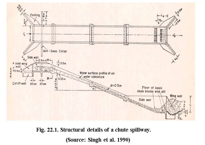
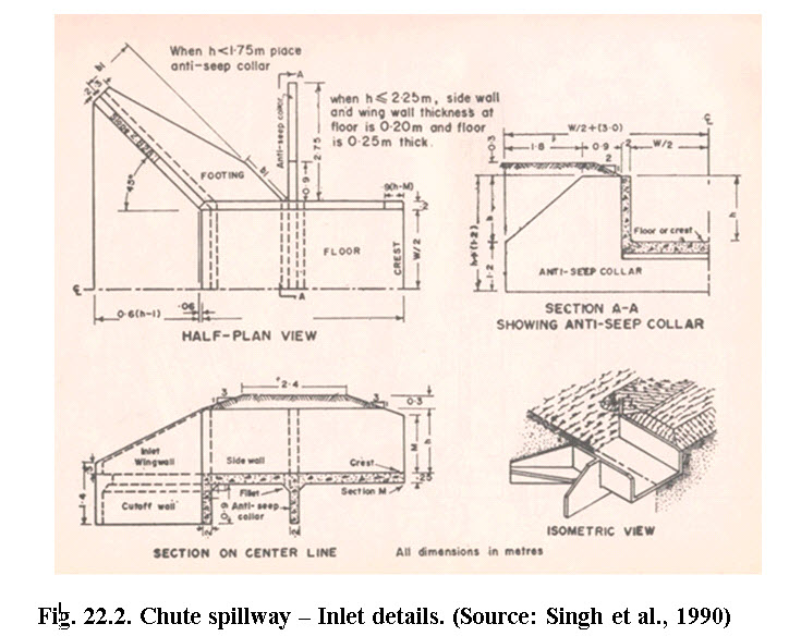
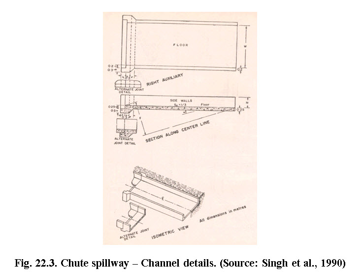
Figs. 22.2 and 22.3 present the inlet and channel details of chute spillway. The design procedure for inlet is more or less similar to that of drop structures except design of stilling basin and tail water. The channel is designed in such a way that the flow remains sub-critical.
22.2 SAF Stilling Basin Design
The Saint Anthony Falls (SAF) stilling basin, shown in Fig. 22.4, provides chute blocks, baffle blocks, and an end sill that allows the basin to be shorter than a free hydraulic jump basin. It is recommended for use at small structures such as spillways, outlet works, and canals where the Froude number at the dissipater entrance is between 1.7 and 17. The reduction in basin length achieved through the use of appurtenances is about 80 percent of the free hydraulic jump length. The SAF stilling basin provides an economical method of dissipating energy and preventing stream bed erosion.
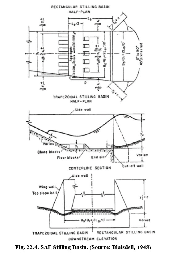
Referring Fig. 22.4, the dimensions of different components of SAF stilling basin are given under (Blaisdell, 1948):
- Length of stilling basin (LB) is given by
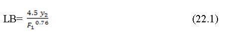
This equation is valid for the Froud number ranging between 1.7 to 17. The Froud number can be calculated by the equation, F1 =![]() , in which y1 represents the height of chutes and floor blocks.
, in which y1 represents the height of chutes and floor blocks.
2. Width and spacing of the chutes as well as floor blocks = 0.75y1
3. Distance from the upstream end of the stilling basin to the floor block =
4. No floor blocks should be place closer tothe side walls thany1.
5. The floor blocks should be placed at downstream side from the openings between the chute blocks.
6. The height of the end sill should be equal to 0.07 y2,
7. The actual depth of tail water above the stilling basin can be computed by the equation,
for F1= 1.7 to 5.5 (22.2a)
for F1= 5.5 to 11.0 (22.2b)
for F1= 11 to 17 (22.2c)
8.The height of the side wall above the maximum tail water depth is given by
9.Height of wing wall should be equal to the height of stilling basin’s side wall.
10.The top of wing wall should have a slope of 1:1.
11. The wing wall may be placed at an angle of 450 to the centre line of the outlet.
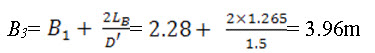
12. The width of stilling basin at the downstream end (B3) is given by
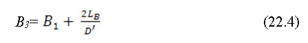
In which, D' is the slope of flare given to the side wall and B1 = basin width at upstream equal to chute channel width.
13. In order to make structure safe against sliding, a cutoff wall of nominal depth should be provided at the end of stilling basin.
14. In the design of stilling basin the effect of entrained air should be neglected.
22.3 Structural Design
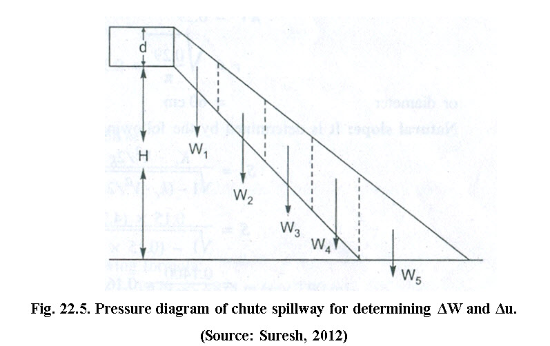
Structural design of chute spillway deals with the determination of the thickness of stable chute floor. The thickness of floor is initially assumed to check the stability at every section. The structure is considered to be stable, when the weight of the structure (ΔW) is greater than the uplift pressure due to water (Δu) (i.e. ΔW > Δ u). The uplift pressure over the structure is calculated by drawing the pressure diagram. The pressure is assumed equal to the depth of flow and zero at the beginning of the structure and at the outlet end, respectively. The pressure diagram is then divided into a number of equal parts and area of each part is calculated. The uplift pressure is obtained by multiplying the density of water with area of pressure diagram. The detail is shown in Fig. 22.5.
Example 22.1:
Design a chute spillway for a gully head with a drop of 3.5 m, laid on a 1.5:1 slope. The slope of flare given to the side wall is 1.5:1. The width of the gully is 4.5 m and the catchment area is 25 ha. From the records, it has been found that the maximum intensity of rainfall based on a 50 – year recurrence interval is 10cm / h, for the duration equal to the time of concentration. The runoff coefficient for the rational formula is 0.35. The spillway is to have a straight inlet with a depth of flow of 0.70 m, and a SAF stilling basin at the outlet.
Solution:
The peak flow rate for the design of the structure is determined by using the Rational formula:
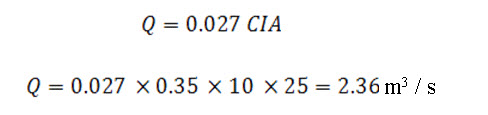
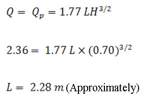
Inlet width
The spillway is to be provided with straight inlet, therefore, the flow discharge through it is
Flow velocity at the stilling basin toe is 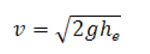
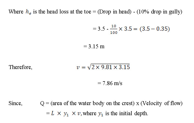
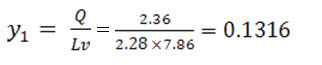
Therefore, the initial depth of flow,
Froud number, 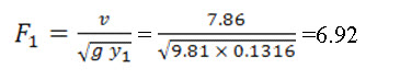
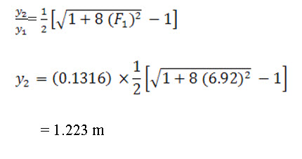
Sequent depth y2, the depth of water after hydraulic jump is determined by the following formula;
Design Dimensions
- Floor and chute blocks height = y1 = 0.1316 m
- Spacing and width between floor and chute blocks = 0.75y1
= 0.75 x 0.1316 = 0.0987 m
3. Distance (minimum) of the floor blocks from the side walls = 0.375 x
= 0.375 x 0.1316
= 0.05 m
4. Tail water depth over the stilling basin,
y'2=0.85y2=0.85 x 1.223 =1.039 m
5. Stilling basin length = LB 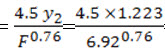 = 1.265 m
6. Side wall and stilling basin height = 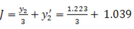 = 1.44 m
7. Transverse sill height = 0.07 x y2= 0.07 x 1.223 = 0.0856 m
8. Side wall freeboard to be provided above the tail-water depth = 0.41 m
9. Wing wall height = stilling basin side wall height = 1.44 m
10. Width of stilling basin
Structural Design
The weight of the structure should be more than the uplift force. Assume a rectangular channel section, and make thickness of the material 15 cm. The details of the structure pressure diagram shown in Fig. 22.6. The uplift pressure head on the channel of the chute is divided into four sections. Since the channel slope is 1.5:1, therefore, the total horizontal width of the sloping channel section is 5.25 m. Dividing it into 4 equal sections, the water body in each section will have a horizontal width of 1.3125 m.
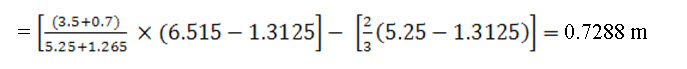
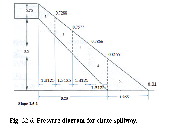 The head at these sections are calculated as under, for example, the head in the first case is
Similarly, the values of the heads for rest of the sections are calculated (see Fig. 22.6).
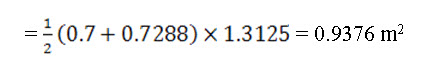
The area of water in each section which will have the shape of a trapezium,
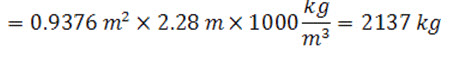
Therefore the uplift force in the first section = water area × width of the channel × density of water
The length of total channel 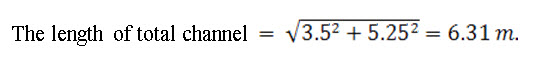
Length of each section = 6.31/4 = 1.577 m.
Width of channel section = 2.28 m.
The weight of the section of the structure
= Cross-sectional area of the section x thickness of concrete x density of concrete =1.577 x 2.28 x 0.15 x 2300 = 1240 kg
Weight of the two sides of the wall on each section = 2(1.577×1.44×0.15×2300)
=1567 kg
Total weight of each section = (1567+1240) = 2807 kg
Weight of the Stilling Basin
Weight of the base = LB x B3 x Thickness X Density of concrete
Weight of the base = 1.265 x 3.96 x 0.15 x 2300 =1728 kg
The height of the side walls of the stilling basin = 1.44 m
Weight of the side walls = (1.265×1.44×0.15×2300) ×2 = 1257 kg
Total weight of the stilling basin = 1728 +1257 = 2985 kg
The computations pertaining to each section and the associated structure stability are all shown in a tabulated form.
Table 22.2. Cumulative value for each section
|
Section no. |
Head of each section upstream (m) |
Head of each section downstream (m) |
Horizontal width of the water body (m) |
Each section area (m2) |
Uplift force (kg) |
Cumulative uplift force (kg) Δ u |
Weight of each section (kg) |
Cumulative weight of structure (kg) ΔW |
Stability of structure |
|
(1) |
(2) |
(3) |
(4) |
(5) |
(6) |
(7) |
(8) |
(9) |
(10) |
|
1. |
0.7 |
0.7288 |
2.28 |
0.93765 |
2137.84 |
2137.842 |
2807 |
2807 |
Safe |
|
2. |
0.7288 |
0.757751 |
2.28 |
0.975549 |
2224.25 |
4362.094 |
2807 |
5614 |
Safe |
|
3. |
0.757751 |
0.786627 |
2.28 |
1.013498 |
2310.77 |
6672.871 |
2807 |
8421 |
Safe |
|
4. |
0.786627 |
0.815503 |
2.28 |
1.051398 |
2397.18 |
9070.057 |
2807 |
11228 |
Safe |
|
5. |
0.815503 |
0.01 |
3.96 |
0.52213 |
2067.63 |
11137.69 |
2985 |
14213 |
Safe |
Therefore the structure designed is safe.
References
Chanson, H. (2002). Hydraulics of Stepped Chutes and Spillway, Taylor and
Francis Publication, pp 199-284.
Das, G. (2000). Hydrology and Soil Conservation Engineering, Prentice-Hall
India, pp 356-377
Hydraulic Design of Energy Dissipaters for Culverts and Channels. (2000). Hydraulic Engineering, Circular no.14, Third edition.
Singh, G, Venkataramanan, C., Sastry, G., and Joshi, B. P. (1990). Manual of Soil and Water Conservation Practices. CSWCR&TI, Dehradun.
Suresh, R. (1993). Soil and Water Conservation Engineering, Standard Publishers Distributors, New Delhi, pp 190-243
Suggested readings
Blaisdell, F. W. and Mortaz, A. F. (1961). Soil and Water Conservation- Erosion Control Structures, Agricultural Engineering Handbook, McGraw-Hill, New York
Blaisdell, F.W., The SAF stilling basin, Agricultural Handbook, No., 156, USDA., 1948
USDA, SCS Engineering. Handbook, sec. 14, Oct 28, 1985.
http://www.fhwa.dot.gov/engineering/hydraulics/pubs/06086/hec14.pdf
Last modified: Tuesday, 11 February 2014, 11:56 AM