Site pages
Current course
Participants
General
MODULE 1. Fundamentals of Soil Mechanics
MODULE 2. Stress and Strength
MODULE 3. Compaction, Seepage and Consolidation of...
MODULE 4. Earth pressure, Slope Stability and Soil...
Keywords
29 March - 4 April
5 April - 11 April
12 April - 18 April
19 April - 25 April
26 April - 2 May
LESSON 10. Mohr-Coulomb Failure Theory
10.1. Mohr-Coulomb failure theory
Soil generally fails in shear. At the failure surface, shear stress reaches the shear strength (tf) of the soil. It the failure surface, sliding between the particles takes place as shown in Figure 10.1. The resistance that the soil offers during deformation is mainly due to the shear resistance between the particles at their contact points at the failure surface. No crushing of individual particle takes place. According to Mohr-Coulomb failure criterion, the shear strength of the soil can be expressed as:
\[{\tau _f}=c + \sigma \tan \emptyset\] (10.1)
where c is the cohesion and Ø is the angle of internal friction of the soil. σ is the applied normal stress. The line satisfying the Eq. (10.1) is called the Mohr-Coulomb failure envelop (as shown in Figure 10.2 with red color). In Figure 10.2, it is shown that tf is the maximum stress soil can take without failure under an applied vertical stress σ (with blue color). Figure 10.3 shows the Mohr circle of two soil elements one at the failure surface (red color) and one at any other location (blue color). The Mohr circle touches the failure envelop incase of soil element taken from location of failure surface, whereas Mohr circle of the soil element taken from other than the location of failure surface is situated below the failure envelop. Keeping σ3 constant, if vertical stress (σ1) increases the Mohr Circle becomes larger and finally it will touch the failure envelop and failure will take place (as shown in Figure 10.4). Figure 10.5 shows the Mohr circle for total stress and effective stress condition. The Eq. (10.1) represents the shear strength in terms of total stress (σ). In terms of effective stress (σ' = σ - u), the shear strength of the soil can be expressed as:
![]()
where u is the pore water pressure.
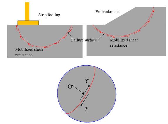
Fig. 10.1. Failure surface and shear resistance.
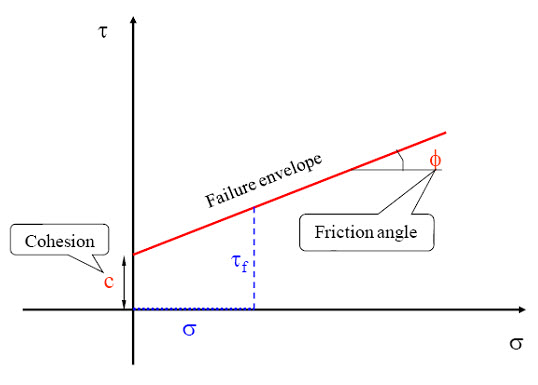
Fig. 10.2. Mohr-Coulomb failure criterion and failure envelop.
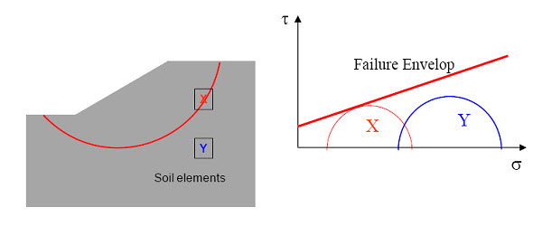
Fig.10.3. Mohr circles of different soil elements
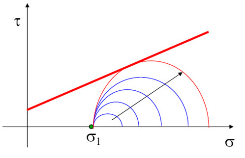
Fig. 10.4. Mohr circles for different stress condition
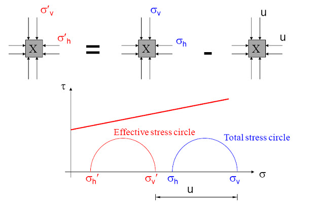
Fig. 10.5. Mohr circles for total stress and effective stress condition
References
Ranjan, G. and Rao, A.S.R. (2000). Basic and Applied Soil Mechanics. New Age International Publisher, New Delhi, India
PPT of Professor N. Sivakugan, JCU, Australia
Suggested Reading
Ranjan, G. and Rao, A.S.R. (2000) Basic and Applied Soil Mechanics. New Age International Publisher, New Delhi, India
Arora, K.R. (2003) Soil Mechanics and Foundation Engineering. Standard Publishers Distributors, New Delhi, India
Murthy V.N.S (1996) A Text Book of Soil Mechanics and Foundation Engineering, UBS Publishers’ Distributors Ltd. New Delhi, India
PPT of Professor N. Sivakugan, JCU, Australia (eng1.jcu.edu.au/research/compgeo/strength.pps).
Last modified: Monday, 23 September 2013, 9:00 AM