Site pages
Current course
Participants
General
MODULE 1. Analysis of Statically Determinate Beams
MODULE 2. Analysis of Statically Indeterminate Beams
MODULE 3. Columns and Struts
MODULE 4. Riveted and Welded Connections
MODULE 5. Stability Analysis of Gravity Dams
Keywords
5 April - 11 April
12 April - 18 April
19 April - 25 April
26 April - 2 May
LESSON 25. Rivet Joints: Basic Concept
Connections are the most important part of a structure. In this module we will learn analysis and design of two different types of connection commonly used in practical structures; (i) Riveted connection; and (ii) Welded connection.
In this lesson we will discuss different kinds of riveted joints and their failure mechanisms. Design of riveted connection will be discussed in the next lesson.
25.1 Types of Riveted Joints
Riveted joints are mainly of two types,
25.1.1 Lap joints
In lap joints two members which are to be connected are overlapped and rivets are inserted in the overlapping portion. Different types of riveted lap joints are illustrated in Figure 25.1.
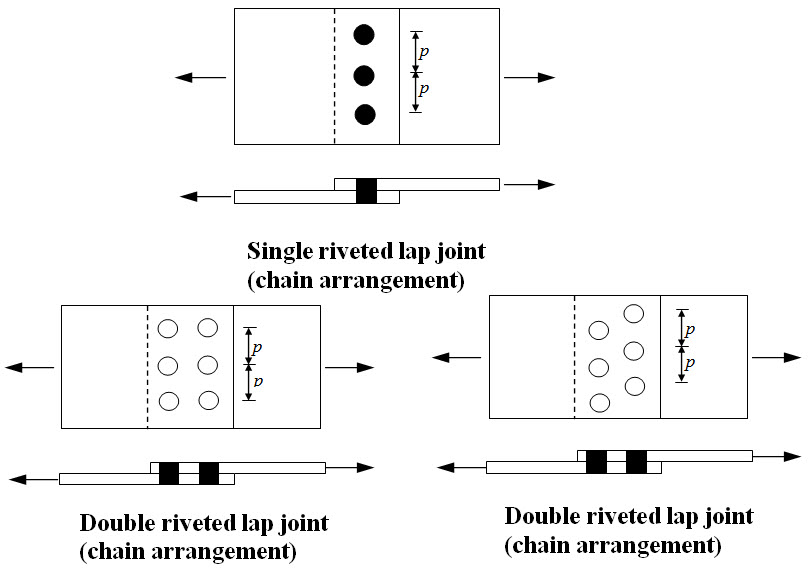 Fig. 25.1.
25.1.2 Butt joints
In butt joints, the members to be connected are placed against each other without forming any overlap and then connected together through one or more additional cover plates. When the cover plate is provided on one side of the joint it is called single cover butt joint and when provided on both sides of the joint, it is called double cover butt joint. Different types of riveted butt joints are illustrated in Figure 25.2.
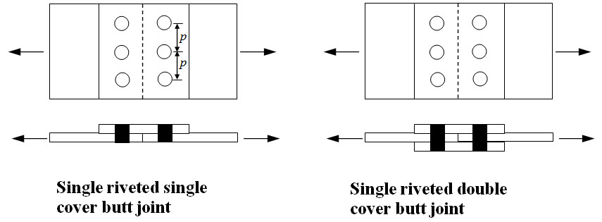
Fig. 25.2.
The distance between the centers of two adjacent rivets in a row is called pitch (p).
25.2 Failure Mechanism
A riveted joint is said to be failed when either of the rivets or the connected plates fail. Therefore strength of a riveted joint is determined by taking into account of all possible failure mechanisms. The possible failure mechanisms are illustrated below,
25.2.1 Tearing of plate
Due to the presence of holes the effective width of the plate decreases and consequently the tensile stress increases. If the induced tensile stress in the plate is more than the allowable value the plate fails in tension as shown in Figure 25.3..
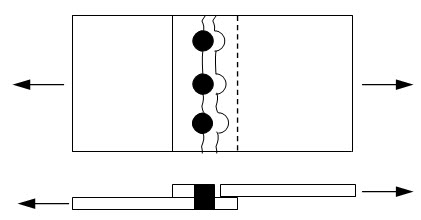
Fig. 25.3.
25.2.2 Tearing of plate at the edge
If the row of rivets is very close the edge of the plate then the plate may fail as shown in Figure 25.4.
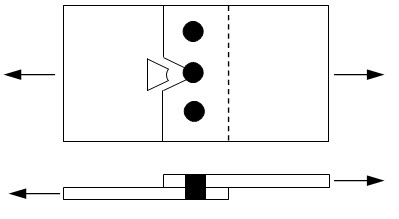
Fig. 25.4.
In order to prevent such failure a minimum distance (usually 1.5 times the diameter of the hole) of the row of rivets from the edge of the plate is maintained.
25.2.3 Shearing of rivet
The rivet may fail in shear as shown in Figure 25.5.
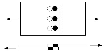
Fig. 25.5.
25.2.4 Bearing of rivet
If the stress at the contact surface between the rivet and the plate reaches the allowable bearing stress the rivet may fail in bearing as depicted in Figure 25.6.
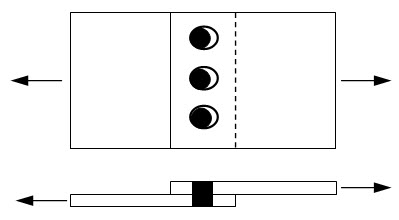
Fig. 25.6.
25.2.5 Failure mechanism in multiple riveted joints
In a multiple riveted joints, an individual row may fail in any mechanism as mentioned above. However failure of one row may not necessarily lead to complete joint failure. For instance, in the double riveted joint as shown in Figure 25.7, tearing of plate first occurs at row 1. However the joint as whole may not fail as the plates are still connected through the rivets at row 2. In order to have a complete failure, row 2 has to fail either by shear or by crushing and therefore strength of both the rows must be considered in determination of strength of joint. On the other hand if tearing of plate occurs as illustrated in Figure 25.8, the joint completely fails irrespective of row 1. In this case the strength of the joint will govern only by the strength of row 2.
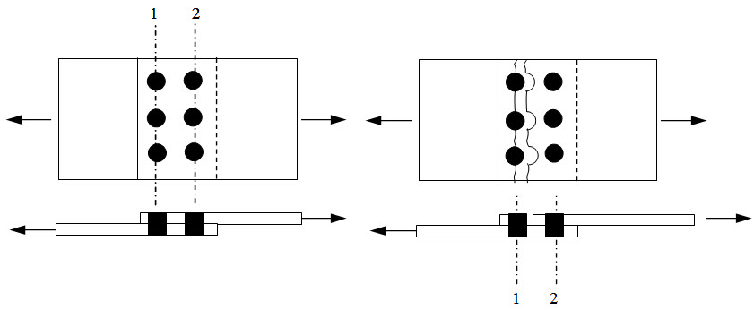
Fig. 25.7.
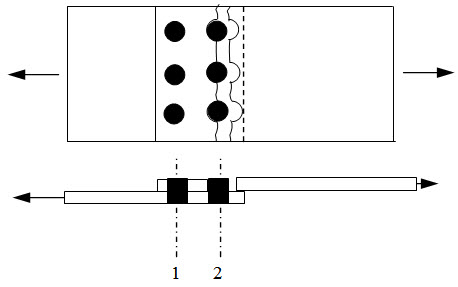
Fig. 25.8.
While determining the strength of a riveted joint (single or multiple) failure in all possible combination has to be considered.
25.3 Efficiency
In absence of rivet the maximum load that can be carried by the plate is σtpt . However presence of rivet reduces the strength. Efficiency of riveted joint is defined as,
\[{\rm{Efficiency }}(\eta )={{{\rm{strength of joint}}} \over {{\sigma _t}pt}}\]
where, t and σt are respectively the allowable tensile stress and thickness of the plate.
Suggested Readings
Subramanian, N. (2008). Design of Steel Structures. Oxford University Press.
Duggal, S.K. (2010). Limit State Design of Steel Structures. First Edition, Tata McGraw - Hill Education.
Last modified: Saturday, 21 September 2013, 6:55 AM