Site pages
Current course
Participants
General
Module 1: Watershed Management – Problems and Pros...
Module 2: Land Capability and Watershed Based Land...
Module 3: Watershed Characteristics: Physical and ...
Module 4: Hydrologic Data for Watershed Planning
Module 5: Watershed Delineation and Prioritization
Module 6: Water Yield Assessment and Measurement
Module 7: Hydrologic and Hydraulic Design of Water...
Module 8: Soil Erosion and its Control Measures
Module 9: Sediment Yield Estimation/Measurement fr...
Module 10: Rainwater Conservation Technologies and...
Lesson 14 Design of Earthen Embankments and Diversion Structures
14.1 Hydrologic and Hydraulic Design of Earthen Embankments
Earthen embankments play a major role in watershed planning and management. In this section, the design of small earthen embankments viz., tank bunds -which are very useful in watershed management, is discussed.
14.1.1 Tank Bunds
Tank bund is an embankment of low height. Generally it is made of earth. Since earth of various types is available, tank bunds may be constructed using principles adopted for construction of earth dams. Generally three types of tank bunds are constructed. They are:
(a) Homogeneous Tank Bund (Type A): Uniform and homogeneous materials are used in the construction of these type of earthen embankments. It is constructed with relatively flat side slopes from the consideration of stability. Most of the bunds belong to this type [Fig. 14.1].
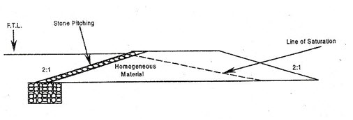
Fig. 14.1. Homogeneous Tank Bund (Type A).
(Source: Patel and Shah; 2008)
When the height of tank bund is more than 5 m, the section is modified suitability with seepage checking trenches, blankets, toe drains etc. s need to be applied
(b) Zoned Tank Bund (Type B): When earth of different types is locally available the bund may be constructed by dividing the section in different zones [Fig. 14.2].
Outer zone is generally made of pervious material indicated as ‘P’ in Fig. 14.2. The inner zone is made of impervious material. It is indicated as ‘I’ in the same figure.
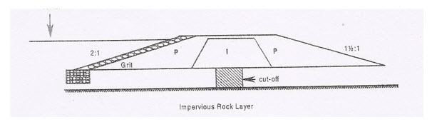
Fig. 14.2. Zoned Tank Bund (Type B). (Source: Patel and Shah; 20080
(c) Diaphragm Type Tank bund (Type C): Many times zoning is done by providing a central core wall, called diaphragm. It is generally constructed with masonry or concrete [Fig. 14.3].
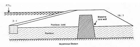
Fig. 14.3. Diaphragm Type Tank Bund (Type C).
(Source: Patel and Shah; 2008)
In such types of tank bunds, the diaphragm is taken quite deep into the foundation preferably up to the impervious stratum.
Design of Tank Bunds
Although high tank bunds are designed on the principles similar to design of earth dams, low tank bunds are constructed using empirical dimension. Commonly adopted bund dimensions are given in Table 14.1.
Table 14.1. Empirical Dimensions for Tank Bund Design (Source: Patel and Shah; 2008)
|
Height of the Tank Bund above the Deepest Bed (m) |
Freeboard (m) |
Top Width (m) |
|
More than 7.5 |
1.8 |
2.7 |
|
6.0 to 7.5 |
1.5 |
1.8 |
|
4.5 to 6.0 |
1.2 |
1.5 |
|
2.5 to 4.5 |
0.9 |
1.2 |
The side slopes of the tank bund are kept quite mild. A slope of 2:1 (Horizontal: Vertical) is commonly used. However, for lesser heights steeper slopes may be adopted.
Like earth dams, the upstream face of the tank bund is generally given stone pitching, also called revetment. Thickness of the pitching may vary from 0.3 to 0.6 m. A toe is also provided to support the sloping face. General arrangement is already shown in Fig.s 14.1 to 14.3.
Storage Capacity of a Tank: Storage capacity of a tank can be calculated using trapezoidal formula. It is stated as:
![]()
Here,
V is volume enclosed between two adjacent contours.
A1 & A2 are the areas enclosed in two contours.
H is the contour interval.
This method is useful in finding capacity between two successive contours only. But since tank bunds are of small heights, the method is quite useful. The effective storage in a tank is the volume between level of the sill of the outlet or the lowest sluice and full tank level.
14.2 Hydrologic and Hydraulic Design of Diversion Structures
It is already mentioned that tanks are small storage structures constructed to meet local requirements. Obviously attempt is not made to store full runoff from the catchment area. It is therefore necessary to make suitable arrangement of diversion structures to pass excess water above Full Tank Level (FTL) safely to the downstream. Diversion structures constructed to provide passage to excess water are called escape weirs or tank surplus weirs.
The water starts spilling over the weir as soon as tank is filled up to its crest. However, due to rush of incoming water the level in the tank rises temporarily above FTL. This new level reached is called Maximum Water Level (MWL). It depends on the extent of flood. For design purposes, MWL is calculated taking into account maximum flood discharge likely to occur and the waterway available at the site of the escape weir. The spilling water is carried down through a channel, which is generally a natural drainage and has enough discharge carrying capacity.
Selection of Site for a Tank Surplus Weir: Following points may be taken into consideration while selecting a site for a tank weir:
(i) Tank surplus weir performs the function of passing excess flow. Therefore it is preferable to locate the weir in a natural saddle away from the tank bund.
(ii) The saddle i.e. the Natural Surface Level (NSL) is approximately at the same level as the FTL. It should be given first preference.
(iii) Hard foundation -if available at the site, reduces the cost of construction of bed protection works.
(iv) When a site away from tank bund is not available, as far as possible weir may be located on one end of the tank bund.
(v) Surplus weir may be housed in the body of the tank bund, only as a last resort.
(vi) Care should be taken to see that escape channel carrying surplus water is not likely to damage the cultivated areas.
Types of Weirs: Escape weirs constructed in tank irrigation system is similar to a diversion weir or an anicut constructed across the river channel. It may be constructed with either masonry or rock fill or concrete depending upon the availability of construction material and site conditions.
Masonry Weirs: This type of weir is most commonly used in a tank irrigation system. Masonry weirs are generally constructed as vertical drop weirs and are designed as gravity weirs. Self-weight of the body wall is the only restoring external force and it resists all destabilizing forces like water pressure, uplift etc. On the body of the weir, dam stones may be erected to enable extra storage. Depending upon the site conditions, masonry weirs may be constructed in three ways as given below.
Masonry Weir with Horizontal Floor: a drop is provided as shown in Fig. 14.4. This weir type is suitable when hard rock is available in the foundation and the height of the weir is less than 1 m or so.
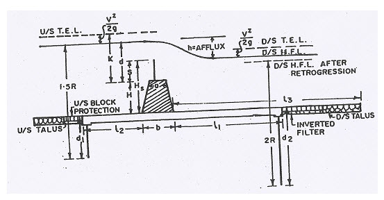
Fig. 14.4. Masonry weir with horizontal floor.
(Source: Punmia and Pande, 1992)
Masonry Weir with Depressed Floor: This type of weir is similar to one explained above except that the downstream apron is depressed below the ground level as shown in Fig. 14.5. By depressing the apron below ground level a sort of stilling pond is formed. It helps in dissipating the energy of water spilling over the crest of the weir. This type of arrangement is generally used for weirs with greater heights of more than 2.5 m. They are designed like a canal fall with the inclined floor generally having a slope of 4 H: 1 V.
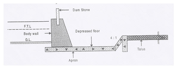
Fig. 14.5. Masonry weir with depressed floor.
(Source: Patel and Shah, 2008)
Masonry Weir with Stepped Floor: When the topography is such that there is no space for constructing either horizontal or depressed floor apron, weir with a stepped apron may be constructed as shown in Fig. 14.6. It is generally having a step and is suitable for low heights of body wall.
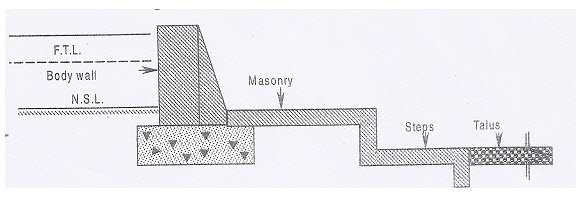
Fig. 14.6. Masonry weir with stepped apron. (Source: Patel and Shah, 2008)
Rockfill Weir: They are constructed as shown in with locally available dry rockfill, if such material is available in sufficient quantity. To support the rockfill masonry, retaining walls are constructed as shown in Fig. 14.7. Top surface of the weir is plastered. This type of weir acquires a very wide cross section because the slopes are quite flat [i.e., 1 V: 4H on the upstream side and 1 V: 20 H on the downstream side, generally].
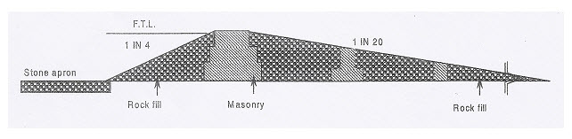
Fig. 14.7. Rockfill weir. (Source: Patel and Shah, 2008)
Concrete Weir: A typical profile of concrete weir is shown in Fig. 14.8. This type of weir is constructed with reinforced concrete to make the section monolithic. weir is constructed mostly where foundations are pervious.
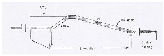
Fig. 14.8. Concrete weir. (Source: Patel and Shah, 2008)
In this type of weir, a sloping glacis is generally provided on the downstream side. It helps in creating a hydraulic jump on the sloping face. When hydraulic jump is created, excessive supercritical energy gets dissipated. Thus the bed below the weir is protected.
Design of Tank Weirs
Maximum Flood Discharge of Tank: Since the weir has to safely pass the excess flow downstream, estimation of peak flow becomes the first step in design of tank weirs. Catchment area of tank is generally small and fan shaped it is difficult to measure the discharge. Therefore it is estimated using empirical formulae. In North India, Dicken’s formula is used while in South India, Ryve’s formula is used. Dicken’s formula is as given below:
Q = C.A3/4 (14.2)
where,
Q is peak flow in cumec,
A is catchment area in km2 and
C is a constant.
The values of C are as given below:
C=11.4 for North India; C=13.9 to 19.5 for Central India and C = 22.2 to 25 for Western India
Ryve’s formula for peak discharge (Q) is stated as below:
Q = C. A2/3 (14.3)
where,
Q is peak flow in cumec,
A is catchment area in km2,
C is a constant, as given below.
C = 6.75 for areas within 24 km from the coast.
C = 8.45 for areas within 24-161 km from the coast.
C = 10.1 for limited hilly areas.
This formula can be applied for a free catchment. Fortanks in series or interconnected tanks the formula needs correction. Modified formula for discharge (Qm) is:
Qm = C.A2/3 - Cm. Am2/3 (14.4)
where Am is the catchment area in km2 intercepted by upstream tank;
Cm is the new coefficient, whose value varies from 0.2 to 0.33.
Waterway of the Weir
The weirs constructed are generally broad crested weirs and the formula which gives discharge (Q) over broad crested weir can be used. Generally, the velocity of approach is neglected. The discharge formula is in the following form:
Q = C.L.H3/2 (14.5)
where,
L is the weir length in m;
H is the design head over weir given by (MWL - FTL) in m;
C is a coefficient, as given below.
C = 1.84 for weir crest up to 0.9 m width.
C = 1.66 for weir crests more than 0.9 m width.
C = 1.66 for crests with dam stones.
C = 1.47 for crests with d/s sloping face.
Length of Apron: Usually the length of the horizontal downstream apron is kept as 2(D + H) from the toe of body wall, where D is the height of the body wall above floor and H is the maximum water head over the crest of the wall. An additional factor of safety of 1.5 is provided when important areas lie below the surplus weir. Then horizontal downstream apron length becomes 3(D + H).
Length of Stone Pitching: Generally 3(D + H) to 5(D + H) length of stone pitching is provided on the downstream side of apron in continuation of the horizontal downstream apron. Greater length is provided, when there is a weaker foundation material.
Keywords: Earthen embankments, Diversion structures, Tank bunds, Escape weirs, Masonry weirs, Rockfill weirs, Tank Weirs.
References
Patel, A. S. and Shah, D. L. (2008). Water Management, New Age International Publishers, pp. 125-131.
Punmia, B. C. and Pande, and Lal, B. B. (1992). Irrigation and Water Power Engineering, Lakshmi Publications, New Delhi, pp.124-125, 552-560.
Suggested Reading
Sharma, H. D. (1991). Embankment Dams, Oxford & IBH Publishing.
Last modified: Thursday, 6 February 2014, 10:39 AM