Site pages
Current course
Participants
General
MODULE 1. BASIC CONCEPTS
MODULE 2. SYSTEM OF FORCES
MODULE 3.
MODULE 4. FRICTION AND FRICTIONAL FORCES
MODULE 5.
MODULE 6.
MODULE 7.
MODULE 8.
19 April - 25 April
26 April - 2 May
LESSON 4 RESOLUTION OF A FORCE INTO COMPONENTS
4.1 RESOLUTION OF A FORCE INTO COMPONENTS
A given force F can be resolved into (or replaced by) two forces, which together produces the same effects that of force F. These forces are called the components of the force F. This process of replacing a force into its components is known as resolution of a force into components. A force can be resolved into two components, which are either perpendicular to each other or inclined to each other. If the two components are perpendicular to one another, then they are known as rectangular components and when the components are inclined to each other, they are called as inclined components. The resolution of force into components is illustrated as follows.
4.1.1 Resolution of a Force into Rectangular Components
Consider a force F acting on a particle O inclined at an angle Ө as shown in Fig.4.1(a). Let x and y axes can be the two axes passing through O perpendicular to each other. These two axes are called rectangular axes or coordinate axes. They may be horizontal and vertical or inclined as shown in Fig. 4.1(b).
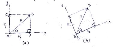
Fig. 4.1 Resolution of force into rectangular components
The force F can now be resolved into two components Fx and Fy along the x and y axes and hence, the components are called rectangular components. Further, the polygon constructed with these two components as adjacent sides will form a rectangle OABC and, therefore, the components are known as rectangular components.
From the right angled triangle OAB, the trigonometrical functions can be used to resolve the force as follows:
cos Ө = \[{{OA} \over {OB}}\]
Therefore,
OA = OB × cos Ө
Or
Fx = OA = F cos Ө (4.1a)
sin Ө = \[{{AB} \over {OB}}\]
Therefore,
AB = OB × sin Ө
Fy = OC = AB = F sin Ө (4.1b)
Therefore, the two rectangular components of the force F are:
Fx = F cos Ө and Fy = F sin Ө
The conventional coordinate directions are used for the sign conventions of the components of the force. That is, the components along the coordinate directions are considered as positive components and the one in the opposite direction as negative components. The sign conventions shown in Fig.4.2 are used in general.

Fig.4.2 Sign conventions
Example 4.1: Determine the components of force P = 40 kN along x and y as shown in Fig.4.3.
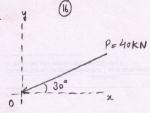
Fig.4.3
Solution: Plot a rectangle OPSQ taking the force P (that is OS) as the diagonal as illustrated in Fig.4.4, the two components Px and Py can be obtained.
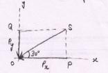
Fig.4.4
Consider the right angle triangle OPQ in which
cos 30° = \[{{OP} \over {OS}}\]
Or
OP = OS cos 30°
Therefore,
Px = P cos 30° = 40 cos 30° = 34.64 KN (←)
sin 30° = \[{{PQ} \over {OQ}}\] = \[{{OS} \over {OQ}}\]
Hence,
OS = OQ sin 30°
Py = P sin 30° = 40 sin 30° = 20 KN (↓)
Note: The directions of Px and Py are obtained based on the direction of P as shown follows:
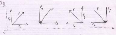
Fig.4.5
Example 4.2: Determine the x and y components of each of the forces shown in the following Fig.4.6
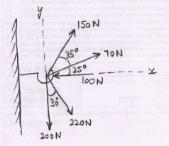
Fig.4.6
Solution: The components of each of the forces are shown in the following table:
|
Force P |
Inclination with x-axis Ө |
x-component Px = P cos Ө |
y-component Py = P sin Ө |
Remarks |
|
100 N |
O° |
100 cos 0° = 100 N (←) |
100 sin 0° = 0 |
The force acts along x-axis, Ө = 0° |
|
70 N |
25° |
70 cos 25° = 63.44 N(→) |
70 sin 25° = 29.58 N (↑) |
- |
|
150 N |
25° + 35° = 60° |
150 cos 60° = 75 N (→) |
150 sin 60° = 129.90 N (↑) |
- |
|
220 N |
90° - 30° = 60° |
220 cos 60° = 110 N (→) |
220 sin 60° = 190.53 N (↓) |
The angle is given with y-axis |
|
200 N |
90° |
200 cos 90° = 0 |
200 sin 90° = 200 N (↓) |
- |
Example 4.3: A force of 150 N is acting on a block as shown in Fig.4.7. Find the components of forces along the horizontal and vertical axes.
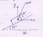
Fig.4.7
Solution: As given in the Fig.7, the force 150 N makes an angle 35° to the plane (shown by a dotted line) and the plane makes an angle 35° to the horizontal that is x-axis. Therefore, the total inclination of the force 150 N with x-axis is 70° [see Fig.4.8]
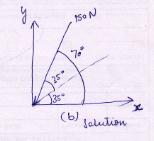
Fig.4.8
Hence the components are:
The x-component of 150 N is,
Px = 150 cos 70° = 51.30 N (←)
The y-component of 150 N is,
Py = 150 sin 70° = 140.95 N (↓)
4.1.2 Resolution of Force into Inclined Components
Sometimes, it is essential to know the components of a force, which are not perpendicular to one another. Such components are known as inclined components or non-rectangular components and they are determined either by triangular law of a force or by using law of parallelogram of forces.
4.1.2.1 Triangular Law of Forces
If two forces P and Q are acting on a particle A, then the two forces can be added or combined to form a single force F by arranging the forces in tip-to-tail fashion and then the single force is obtained by connecting the tail of the first force to the tip of the second force. Fig. 4.9(a) shows two forces acting on A. The two forces can be added either as shown in Fig. 4.9(b) or in Fig. 4.9(c). Considering the force Q as the first force acting at A, its tail end is at A and tip will be, say at B1. Now the tail end of force P is merged with the tip of force Q, that is at B1, and the force P is drawn. The tip of P will be at C (say). Therefore, the force F (addition of forces P and Q) is obtained by joining A (tail of Q) and C (tip of P). The same can also be achieved by considering the force P first and then Q as shown in Fig. 4.9(c). Since, the three forces P, Q and F from the three sides of a triangle, the law is therefore known as triangular law of forces. The single force F combining two forces P and Q is called resultant force.
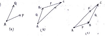
Fig. 4.9 Triangular law of forces
The triangular law of forces is used for the addition of two forces. However, it can be extended to add more than two forces, which extend the law into polygonal law of forces. Fig.4.10 illustrates the addition of four forces P, Q, S and T. As shown in Fig. 4.10(b), F1, is the addition of forces P and Q. The resultant of forces P, Q and S is obtained by adding F1 and S as presented in Fig.4.10(c) in which triangular law of forces is applied to combine F1 and S. Similarly, F3 is the resultant of P, Q, S and T, which is an addition of F2 and T. It is pertinent to mention that the forces can be taken in any order.
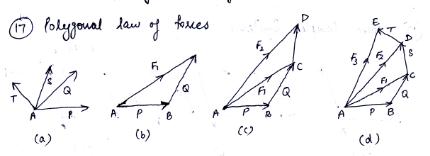
Fig. 4.10 Polygonal law of forces
4.1.2.2 Law of Parallelogram of Forces
This law states that two forces acting on a particle may be replaced by a single force (called resultant of the two forces) obtained by drawing the diagonal of a parallelogram whose two adjacent sides are equal to the given two forces.
Let P and Q be two forces acting on a particle A as shown in Fig.4.11. Constructing a parallelogram ABCD taking P and Q as its adjacent sides, the diagonal AC gives the resultant force R of the two forces P and Q. The expressions for the magnitude and direction of R are obtained as follows:
Considering the right angled triangle ACE, from the Pythagoras theorem,
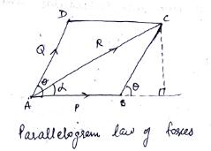
Fig. 4.11 Parallelogram law of forces
(AC)2 = (AE)2 + (EC)2
Also,
AE = AB + BE
Therefore,
(AC)2 = (AB+BE)2 + (EC)2 = (AB)2 + 2 × (AB) × (BE) + (BE)2 + (EC)2
Further, from right angled triangle BCE,
(BE)2 + (EC)2 = (BC)2
Hence,
(AC)2 = (AB)2 + 2 × (AB) × (BE) + (BC)2
Substituting AB = P, BC = AD = Q, BE = BC (cos Ө) = Q cos Ө and AC = R, the magnitude of the resultant force R of the two forces P and Q is
R2 = P2 + 2PQ cos Ө + Q2
Or
R = \[\sqrt {{P^2} + {Q^2} + 2PQcos\theta }\] (4.2a)
The direction of resultant R, defined by the angle α , which the resultant makes with the force P is obtained from right angled triangle ACE, that is
tan α = \[{{CE} \over {AE}}\] = \[{{CE} \over {AB + BE}}\]
Substituting CE = BC (sin Ө) = Q sin Ө along with the values of AB and BE, it yields
tan α = \[{{Q\sin \theta } \over {P + Q\cos \theta }}\]
or α = \[{\tan ^{ - 1}}\left( {{{Q\sin \theta } \over {P + Q\cos \theta }}} \right)\] (4.2b)
The above two laws are used to determine the components of a given force into two inclined components, which are not perpendicular to each other.
Example 4.4: A small block of weight 150 N is placed on an inclined plane which makes an angle, Ө = 30° with the horizontal. What is the component of this weight parallel to inclined plane and perpendicular to inclined plane?
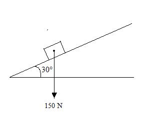
Fig.4.12
Solution: 1. Select the axis
x-axis parallel to inclined plane
y-axis perpendicular to inclined plane
2. Draw the force diagram,
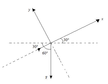
Fig. 4.13
3. Find the force components,
F= 150 N
α = 60°
Fx = F cos α = 150 cos 60° = 75 N
Fy = F sin α = 150 sin 60° = 129.90 N
4.2 LAMI’S THEOREM
It states that,” If three forces acting at a point are in equilibrium each force will be proportional to the sine of the angle between the other two forces.”
Suppose the three forces P, Q and R are acting at a point O and they are in equilibrium as shown in Fig.14.
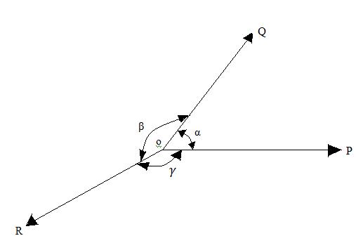
Fig. 4.14
Let α = Angle between force P and Q.
β = Angle between force Q and R.
γ = Angle between force R and P.
Then according to Lami’s Theorem,
P α sine of angle between Q and R α sinβ.
Therefore, \[{P \over {sin\beta }}\] = constant
Similarly =\[{Q \over {sin\gamma }}\] constant and \[{R \over {sin\alpha }}\] = constant
Or \[{P \over {sin\beta }} = {Q \over {sin\gamma }} = {R \over {sin\alpha }}\]
Last modified: Saturday, 7 September 2013, 9:31 AM