Site pages
Current course
Participants
General
MODULE 1. BASIC CONCEPTS
MODULE 2. SYSTEM OF FORCES
MODULE 3.
MODULE 4. FRICTION AND FRICTIONAL FORCES
MODULE 5.
MODULE 6.
MODULE 7.
MODULE 8.
19 April - 25 April
26 April - 2 May
LESSON 16.
16.1 ANALYSIS OF A TRUSS
The analysis of a truss consists of determination of reactions at supports and forces in the members of the truss.
-
The reactions are determined by the condition that the applied load system and the induced reactions at the supports form a system in equilibrium.
-
The forces in the members of the truss are determined by the condition that the every joint should be in equilibrium and so, the forces acting at every joint should form a system in equilibrium.
A truss can be analyzed by the following methods:
-
Method of Joints
-
Method of Sections
-
Graphical Method
16.2 METHOD OF JOINTS
After determining the reaction at the supports, the equilibrium of each joint is considered one by one.
Each joint will be in equilibrium if ∑ V= 0 and ∑ H = 0, these two conditions are satisfied.
Forces in the members will either be tensile in nature or compressive in nature.
The joint is selected in such a way that at any time there are not more than two unknowns.
The direction of an unknown force is assumed.
If the magnitude of force comes out to be positive than assumed direction will be correct.
If the magnitude of force comes out to be negative than assumed direction will be incorrect.
The process is continued until all the joints are considered thereby calculating the forces in all the members of the frame.
Example: Find the forces in the members AB, BC, AC of the truss shown below in Fig.16.1. End A is hinged and B is supported on rollers.
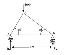
Fig.16.1
Solution: A roller offers a reaction perpendicular to plane of rolling. Let RB is reaction at B. A hinge offers two reaction components one in vertical direction and another in horizontal direction. Since the load of 5O kN acts vertically downward, therefore only vertical direction RA is developed and no horizontal reaction.
From the geometry of the figure, the distance of 50 kN load from A in horizontal direction along AB is AC cos60°.
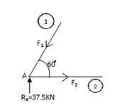
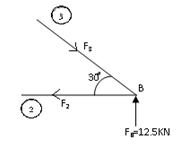
Fig.16.2 Fig.16.3
In ΔACB,
Angle at ACB = 90°
AC = AB cos 60° = 6 × \[{1 \over 2}\] = 3 m
BC = AB sin 60° = 6 × \[{{\sqrt 3 } \over 2}\] = 3 \[\sqrt 3\] m
Distance of 50 kN load from A = AC cos 60° = 3 × = 1.5 m
Taking moments about A, we have
RB × 6 = 50 × 1.5
RB = \[{{50 \times 1.5} \over 6}\] = 12.5 kN
For equilibrium ∑ V = 0, i.e.
RA + RB = 50
RA + 12.5 = 50
RA = 37.5 kN
Considering equilibrium of joint A, first because RA is known and only two unknown forces F1 and F2 are there. At each joint two equation of statical equilibrium are available i.e.
∑ V = 0 and ∑ H = 0.
Let F1 is force produce in the member AC and F2 is the force produced in the member AB as shown in Fig.2. Joint A has to be in equilibrium. Component of force F1 in vertical direction will balance vertical reaction RA. Therefore, the arrow is marked in member (1) in down direction. Applying condition ∑ V = 0 at joint A.
F1 sin 60° = 37.5
F1 = 37.5 × \[{2 \over {\sqrt 3 }}\] = \[{75 \over {\sqrt 3 }}\] = \[{75 \over {\sqrt 3 }}\] × \[{{\sqrt 3 } \over {\sqrt 3 }}\]
= + 25 \[\sqrt 3\] kN (+ve sign indicates that as assumed direction is correct)
= 43.30 kN
As the force F1 is pushing joint A, therefore F1 is compressive force. Mark arrow at joint C as pushing it to show that member AC is compression member (Fig.16.2)
Now applying condition ∑ H = 0 at joint A,
F1 cos 60° = F2
Therefore, F2 = 43.30 × \[{1 \over 2}\] = + 21.65 kN
(again +ve sign indicated that the arrow marked in member AB is correct)
As the force F2 is pulling the joint A, therefore F2 is a tensile force. At B, place arrow marking away from B to show that member AB is a tension member.
Next consider joint B, as shown in Fig.16.3
Let F3 is the force produced in the member BC. The joint B has to be in equilibrium. It must satisfy the two conditions of statical equilibrium viz. ∑ V = 0 and ∑ H = 0. Let us assume the direction of arrow towards B.
Applying ∑ V = 0 at joint B.
F3 sin 30° = 12.5
Therefore F3 = + 25 kN (+ve sign indicates that direction of F3 is correct)
As F3 pushes the joint B, Therefore it is a compressive force.
Now applying second condition ∑ H = 0 at the joint B,
F3 cos 30° = F2
25 × \[{{\sqrt 3 } \over 2}\] = 21.65
21.65 = 21.65 (Check)
Now the forces in the various members are tabulated in the following table.
|
Member |
Force |
|
AB |
Tensile = 21.65 Kn |
|
BC |
Compressive = 25 kN |
|
AC |
Compressive = 43.30 kN |
Forces are marked in the truss, as shown in Fig.16.4. If we take tensile forces as +ve, then compressive force will be –ve.
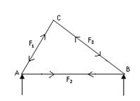
Fig.16.4
Example: Determine the forces in the members of the truss loaded as shown in the Fig.16.5. Also indicate the nature of the force (tensile or compressive).
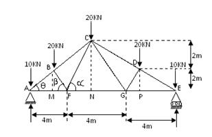
Fig.16.5
Solution: The truss is symmetrical and also loaded symmetrically therefore, reactions RA and RB will be equal. From the condition of equilibrium
∑ V = 0
i.e. RA + RB = 10 + 20 + 20 + 20 +10
2RA = 80
RA = 40 kN, RB = 40 kN
Draw BM and CN perpendicular to AE.
In Δ CAN, tan CAN = = 33.69°
Q = angle at CAN = 33.69°
ΔCFN, tan α = = 2
α = 63.43°
AC = \[\sqrt {A{N^2} + C{N^2}}\] = \[\sqrt {{6^2} + {4^2}}\] = 7.2 m
AB = 3.6 m, BM = 3.6 sin 33.69° = 1.99 m
AM = AB cos Ө = 3.6 cos 33.69° = 2.99 m
MF = AF – AM = 4 – 2.99 = 1.01 m
tan β = \[{{BM} \over {MF}}\] = \[{2 \over {1.01}}\] = 1.98
β = 63.20° = α
Considering joint A, (Fig.16.6). At this joint four forces are acting, out of which two forces AB and AF are unknown. Applying condition of equilibrium at joint A, ∑ V = 0. Resolving all forces in a vertical direction, we have
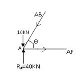
Fig.16.6
10 + AB sin Ө = 40 ..........................(i)
∑ H = 0
Resolving all forces horizontally, we have
AB cos Ө = AF................................(ii)
(Here AF is assumed to be in tension and AB is assumed to be in compression)
From (i), AB × sin 33.69° = 30
Therefore, AB = \[{{30} \over {\sin 33.69^\circ }}\] = \[{{30} \over {0.5547}}\]
= + 54.08 kN (compression)
From (ii), AF = 54.08 cos 33.69°
= 44.99 kN (tensile)
Considering joint B, (Fig.16.7)
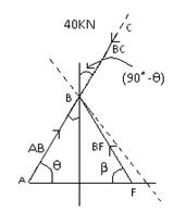
Fig.16.7
Angle ABF = 180° - Ө – β
= 180° - 33.69° - 63.20°
= 83.11°
Resolving all forces perpendicular to ABC,
BF sin 83.11° = 20 sin (90 – Ө)
BF × 0.9928 = 20 cos Ө = 20 × 0.8320
BF = 16.76 kN (compressive)
Resolving all forces along the line ABC,
AB + BF cos 83.11° = BC + 20 cos (90 – Ө)
54.08 + (16.76 × 0.1199) = BC + (20 × 0.5547)
56.089 = BC + 11.094
BC = 44.49 KN (compressive)
Considering joint F, (Fig.16.8)
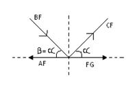
Fig.16.8
Resolving all forces vertically
BF sin α = CF sin α
Therefore, CF = 16.76 kN (tensile)
Resolving all forces in horizontal direction.
FG + CF cos α + BF cos α – AF = 0
Therefore, FG + 16.76 cos 63.20° + 16.76 cos 63.20° - 44.99 = 0
Therefore, FG + 7.56 + 7.56 – 44.99 = 0
FG + 15.12 – 44.99 = 0
FG = 29.87 KN (tensile)
We have analysed half the truss, other half is symmetrical, therefore
AF = EG, AB = ED, BC = DC, BF = DG, CF = CG
|
Member |
Force |
Nature |
|
AB |
54.08 KN |
Compressive |
|
BC |
44.99 KN |
Compressive |
|
CD |
44.99 KN |
Compressive |
|
DE |
54.08 KN |
Compressive |
|
AF |
44.99 KN |
tensile |
|
FG |
29.87 KN |
tensile |
|
GE |
44.99 KN |
tensile |
|
FB |
16.76 KN |
Compressive |
|
FC |
16.76 KN |
tensile |
|
GD |
16.76 KN |
Compressive |
|
GC |
16.76 KN |
tensile |
Last modified: Tuesday, 10 September 2013, 8:46 AM