Site pages
Current course
Participants
General
MODULE 1. BASIC CONCEPTS
MODULE 2. SYSTEM OF FORCES
MODULE 3.
MODULE 4. FRICTION AND FRICTIONAL FORCES
MODULE 5.
MODULE 6.
MODULE 7.
MODULE 8.
19 April - 25 April
26 April - 2 May
LESSON 18.
18.1 INTRODUCTION
The forces in a perfect frame can also be determined by a graphical method. The analytical methods which are discussed in the last lessons give absolutely correct results, but sometimes there is not enough time to analyze the frame using those methods. Then graphical method is used conveniently to get the results.
18.2 GRAPHICAL METHOD
The naming of the various members of a frame are done according to Bow’s notations. According to this notation a force is designated by two capital letters which are written on either side of the line of action of the force. A force with letters L and M on either side of the line of section is shown in Fig.18.1
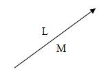
Fig.18.1
The following steps are necessary for the solution of a frame by graphical method:
(i) Making a space Diagram
(ii) Constructing a vector diagram
(iii) Preparing a force table
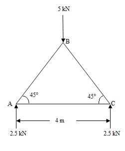
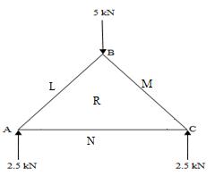
Fig.18.1(a) Given diagram Fig.18.1(b) Space diagram
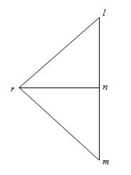
Fig.18.1(c) Vector diagram
(i) Making a space diagram:
The given truss or frame is drawn accurately to some linear scale.
The loads and support reactions in magnitude and directions are also shown on the frame.
Then the various members of the frame are named according to Bow’s notation as shown in the Fig.18.1(b), members AB,BC and AC are to be determined. Fig.18.1(b) shows the space diagram to same linear scale.
The member AB is named as LR and so on.
(ii) Constructing a vector diagram: Fig.18.1(c) shows a vector diagram.
Take any point l and draw lm parallel to LM vertically downwards. Cut lm = 5kN to same scale.
Now from m draw mn parallel to MN vertically upwards and cut mn = 2.5kN to the same scale.
From n draw nl parallel to NL vertically upwards and cut nl = 2.5kN to the same scale.
Now from l, draw a line lr parallel to LR and from n draw a line nr parallel to NR meeting the first line at r. This is vector diagram for joint A. Similarly the vector diagrams for joint B and Joint C can be drawn.
(iii) Preparing a force table: The magnitude of a force in a member is known by the length of the vector diagram for the corresponding member i.e. the length lr of the vector diagram will give the magnitude of force in the member LR of the frame.
Nature of the force is determined according to the following procedure:
(i) In the space diagram, consider any joint. Move round that joint in a clockwise direction. Note the order of two capital letters by which members are named. For example, the members at the joint A in space diagram are named as shown in Fig.18.1(b).(LR,RN and MR).
(ii) Now consider the vector diagram. Move on the vector diagram in the order of the letters (i.e. lr, rn and nl).
(iii) Now mark the arrows on the members of the space diagram of that joint.
(iv) Similarly all joints can be considered and arrows can be marked.
(v) If the arrow is pointing towards the joint, then the force in the member will be compressive whereas if the arrow is away from the joint, then the force in the member will be tensile.
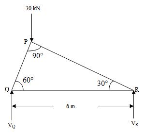
Example: Find the forces in all the members of the given truss shown in Fig.......
Last modified: Tuesday, 10 September 2013, 9:14 AM