Site pages
Current course
Participants
General
MODULE 1. BASIC CONCEPTS
MODULE 2. SYSTEM OF FORCES
MODULE 3.
MODULE 4. FRICTION AND FRICTIONAL FORCES
MODULE 5.
MODULE 6.
MODULE 7.
MODULE 8.
19 April - 25 April
26 April - 2 May
LESSON 20.
20.1 CONCEPT OF SHEAR FORCE AND BENDING MOMENT
- Fig.20.1 shows a cantilever AB whose end A is fixed. Let the cantilever carry a vertical load of 20 KN at C.
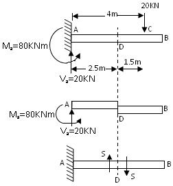
Fig.20.1
For the equilibrium of the cantilever the fixed support at A will provide a vertical reaction vertically upwards, of magnitude Va = 20 KN
Taking moments about A, we have a clockwise moment of 20 × 4 = 80 KNm
Hence the equilibrium of the cantilever, the fixed support at A must also provide a reacting moment or fixing moment of 80 KNm of an anticlockwise order.
Now consider a section D. At this section there is a possibility of failure by shear as shown in Fig.20.1 If such a failure will occurs at section D, the cantilever is liable to be sheared off into two parts. It is clear that the force acting normal to the centre line of the member on each part equals S = 20 kN.
The force acting on the right part of the section D is downward. The resultant force acting on the left part is upward.
The resultant force acting on any one of the parts normal to the axis of the member is called the Shear Force at the section D.
For the case illustrated above the resultant force normal to the axis of the member on the right part of the section is downwards while the resultant force normal to the axis of the member on the left part of the section is upward. Such a shear force is regarded as a positive shear force.
- Let us now study another effect of the load applied on the cantilever. The cantilever is liable to bend due to the load on it.
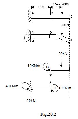
For instance, the cantilever has a tendency to rotate in clockwise direction about A (Fig.20.1). Hence the fixed support at A has to offer a resistance against the rotation.
Taking moments about A, we find that the applied load of 20 KN has a clockwise moment of 20 × 2 = 40 kNm. Hence for the equilibrium of the cantilever, the fixed support at A will provide a reacting or resisting anticlockwise moment of 40 kNm. If the support A is not able to provide such a resisting moment, the cantilever will not be in equilibrium and will, therefore, rotate about A in the clockwise order.
The magnitude of the reacting moment at A depends on the magnitude of the load and the position of the load.
We say that the support A provides the necessary fixing or reacting moment at A, and that at the section A of the beam, there is a bending moment of 20 × 2 = 40 kNm.
Let us no discuss the equilibrium of the part AD (Fig. 20.1) taking moments about D, we get. Moment at fixed end support is equal to 20×1.5=30kNm (clockwise).
Couple = 30kNm
Net moment at D = 40–30=10kNm (anti-clockwise)
Sign conventions for shear force and bending moment
Shear Force: Fig.20.2 shows a simply supported beam AB, carrying a load of 100 kN at its middle point. The reaction at the supports will be equal to 50 kN. Hence RA = RB = 50 kN.
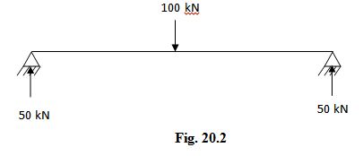
Now imagine the beam to be divided into two positions by the section XX. The resultant of the load and reaction to the left of XX is 50 kN vertically upwards. And the resultant of the load and the reaction to the right of XX is 50 kN downwards.
The shear force at a section will be considered positive when the resultant of the forces to the left of the section is upward or to the right of the section is downward.
The shear force at a section will be considered negative when the resultant of the forces to the left of the section is downward or to the right of the section is upward.
Bending Moment:
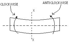
- The banding moment at a section is considered positive if the bending moment at that section is such that it tends to bend the beam to the curvature having concavity at the top.(Fig.20.3)
Fig. 20.3
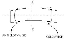
- The bending moment at a section is considered negative if the bending moment at that section is such that it tends to bend the beam to the curvature having convexity at the top.(Fig.20.4)
Fig. 20.4
Positive bending moment is called sagging moment.
Negative bending moment is called hogging moment.
Some important points to remember
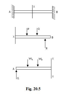
Shear Force: If we have to calculate the shear force at a section the following procedure may be adopted. (see Fig.20.5)
Consider the left or the right part of the section.
Add the forces normal to the member on one of the parts.
If the right part of the section is chosen, a force on the right part acting downwards is positive while a force on the right part acting upwards is negative. For instance, if the S.F. at a section X of a beam is required and if the right part XB be considered the forces P and Q are positive while the force R is negative.
Therefore S.F. at X = P + Q – R
If the left part of the section is chosen, a force on the left part acting upwards is positive and a force on the left part acting downwards is negative.
Therefore S.F. at X = Q – W1 – W2
Bending Moment: To find the bending moment at a section of a beam the following procedure may be adopted.
Consider the left or right part of the section.
Remove all restraints and all forces on the part selected.
Now introduce each force or reacting element one at a time and find its effect at the section.
Treat sagging moment as positive and hogging moment as negative.
- The moment due to every downward force is negative and the moment due to every upward force is positive.
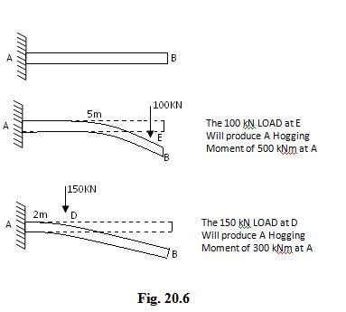
For instance, let the bending moment at the section A of the cantilever AB (Fig.20.6) be required.
If the right part of the section be selected.
Remove the restraints on the part AB.
Introduce the load of 100 kN at E.
The independent effect of the load is to produce a hogging moment of -100 × 5 = -500 kNm
Now consider the independent effect of the 150 kN load at D.
Obviously, this will also produce a hogging moment of – 150 × 2 = -300 kNm
Therefore, Resulting bending moment at A = -500 – 300 = -800 kNm (hogging)
Last modified: Tuesday, 10 September 2013, 10:14 AM