Site pages
Current course
Participants
General
MODULE 1. BASIC CONCEPTS
MODULE 2. SYSTEM OF FORCES
MODULE 3.
MODULE 4. FRICTION AND FRICTIONAL FORCES
MODULE 5.
MODULE 6.
MODULE 7.
MODULE 8.
19 April - 25 April
26 April - 2 May
LESSON 22.
22.1 Shear Force and Bending Moment diagrams for Simply Supported Beams subjected to different types of loading
(i) Simply Supported Beam subjected to concentrated load at mid span
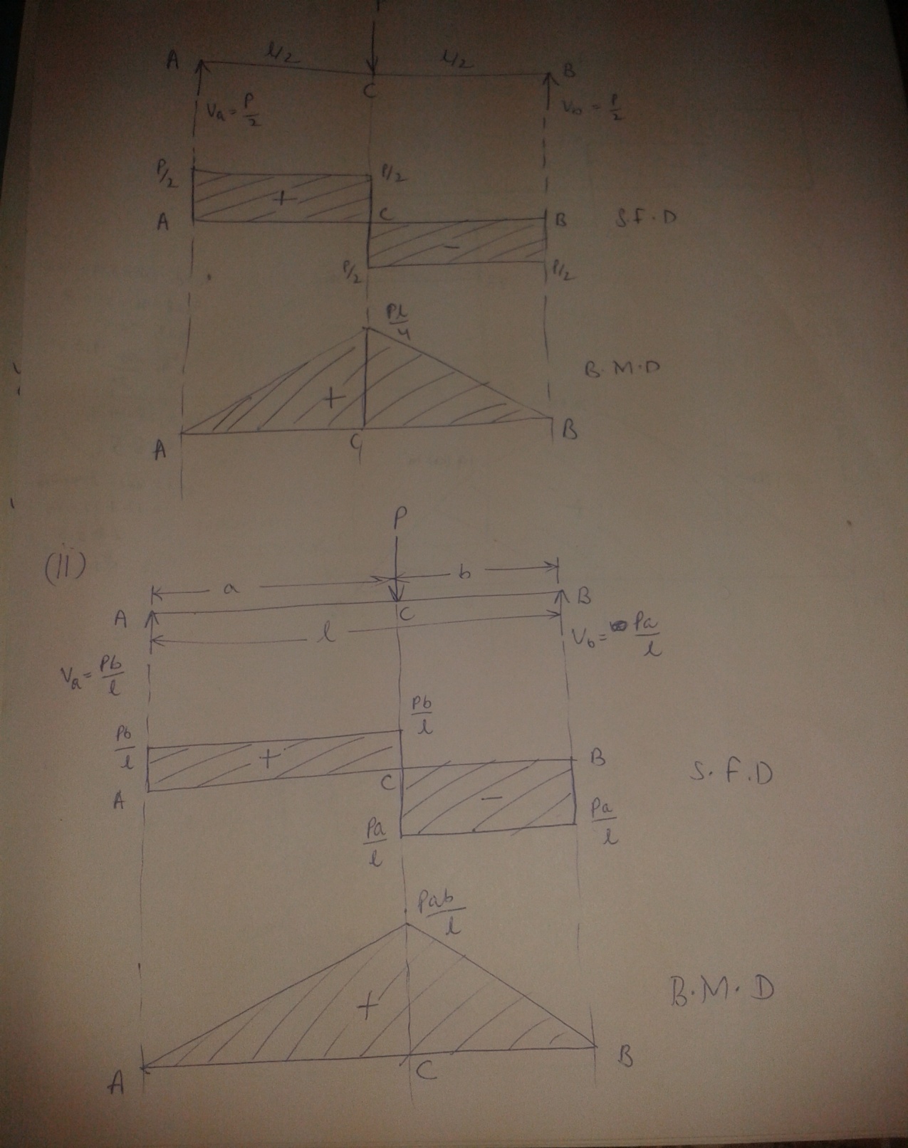
Fig. 22.1 and 22.2
As shown in Fig.22.1, a beam AB simply supported at the ends A and B. The length of the span is l. P is the concentrated load applied at the centre.
The load is placed symmetrical on the span,
Va and Vb are the vertical reactions at A and B.
The reaction at each support will be \[{P \over 2}\]
Therefore, Va = Vb = \[{P \over 2}\]
For any section between A and C,
S.F = Sx = + \[{P \over 2}\]
Similarly for section C and B,
S.F = Sx = - \[{P \over 2}\]
At the point C, the S.F changes from + \[{P \over 2}\] to - \[{P \over 2}\]
For B.M, at any section between A and C distant x from the end A,
Mx = + \[{P \over 2}\] x (sagging moment)
At x = 0, Mx = 0
At x = , Mx = \[{{Pl} \over 4}\]
Hence B.M increases uniformly from zero at A to \[{{Pl} \over 4}\] at C.
Similarly, B.M decreases uniformly from \[{{Pl} \over 4}\] at C to zero at B.
Note: It should be noted that maximum bending moment occurs at mid span (at C), where the shear force changes its sign.
(ii) Simply supported beam subjected to a concentrated load placed eccentrically on the span
Fig.22.2 shows a simply supported beam AB of span l carrying a concentrated load P at C eccentrically. Where AC = a and CB = b
For the equilibrium of the beam,
Taking moments of the forces on the beam about A,
We have Vb . l = Pa
Vb = \[{{Pa} \over l}\]
Va = P - \[{{Pa} \over l} = {{P\left( {l - a} \right)} \over l}\]
Va = \[{{Pb} \over l}\]
We know that a + b = l
At any section between A and C,
S.F, Sx = Va = + \[{{Pb} \over l}\]
for section C and B,
S.F, Sx = - Vb = - \[{{Pb} \over l}\]
Similarly, Bending Moment for any section between A and C
Mx = + \[{{Pb} \over l}x\] (sagging)
At x = 0, Mx = 0
At x = a, Mx = \[{{Pab} \over l}\]
Hence the B.M increases uniformly from zero at the left end A to \[{{Pab} \over l}\] at C. Similarly the B.M will decrease uniformly from \[{{Pab} \over l}\] at C to zero at the right end B.
(iii) Simply supported beam subjected to more than one concentrated load
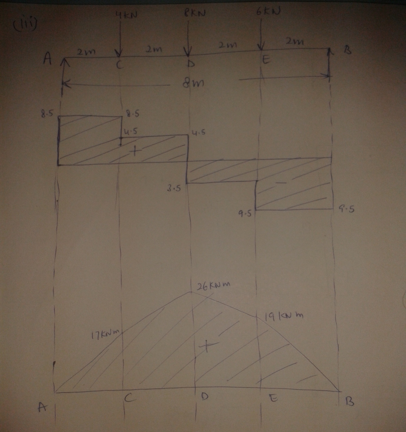
Fig. 22.3
Fig.22.3 shows a simply supported beam AB of span 8m subjected to concentrated loads of 4kN, 8kN and 6kN at distances of 2m, 4m and 6m respectively from support A.
To find the vertical reactions Va and Vb at the supports A and B respectively.
For the equilibrium of beam, Taking moment of the forces on the beam about the left support,
We have,
Vb × 8 = 6 × 6 + 8 × 4 + 4 × 2
Vb = 9.5 kN
Va = total load on the beam – Vb
= 18 - 9.5 = 8.5 kN
We will start from the support A,
S.F between A and C = 8.5 kN
S.F between C and D = 8.5 – 4 = 4.5 kN
S.F between D and E = 8.5 – 4 – 8 = -3.5 kN
S.F between E and B = 8.5 – 4 – 8 – 6 = -9.5 kN
B.M at A = 0
B.M at C = 8.5 × 2 = 17 kNm (sagging)
B.M at D = 8.5 × 4 – 4 × 2 = 26kNm (sagging)
B.M at E = 8.5 × 6 – 4 × 4 – 8 × 2 = 19kNm (sagging)
Note: it can be observed from the S.F and B.M diagrams that the maximum B.M occurs at D where the S.F changes its sign.
(iv)Simply supported beam subjected to uniformly distributed load of w per unit run over the whole span
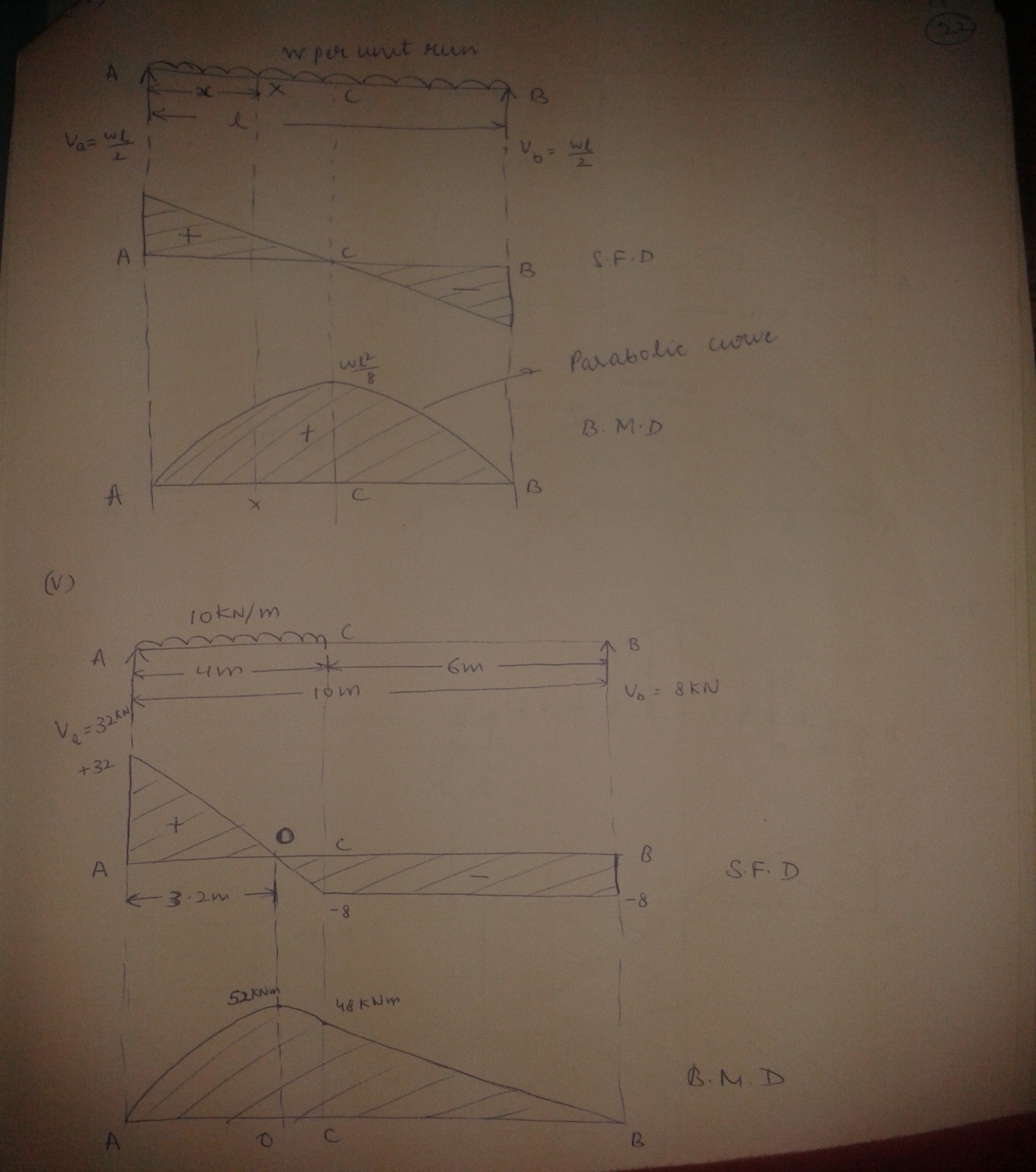
Fig. 22.4 and 22.5
Fig.22.4 shows a simply supported beam AB of span l subjected to uniformly distributed load w per unit run over the whole span.
Since the loading the symmetrical on the span, each vertical reaction equal half the total load on the span.
Therefore, Va = Vb = \[{{wl} \over 2}\]
Consider any section X distant x from the left end A.
S.F and B.M at the section X are given by,
Sx = + Va – wx = + \[{{wl} \over 2}\] – wx
Mx = +Va x - \[{{w{x^2}} \over 2}\] = \[{{wl} \over 2}\] x - \[{{w{x^2}} \over 2}\]
Therefore, Mx = + \[{{w} \over 2}\] x (l - x)
At x = 0, Sx = \[{{wl} \over 2}\] and Mx = 0
At x = l, Sx = \[{{wl} \over 2}\] - wl = - \[{{wl} \over 2}\] and Mx =0
At x = \[{1 \over 2}\] , Sx = \[{{wl} \over 2}\] - \[{{wl} \over 2}\] = 0
And Mx = + \[{w \over 2}\] . \[{l \over 2}\] \[\left( {l - {l \over 2}} \right)\] = + \[{{w{l^2}} \over 8}\]
The S.F diagram is straight line. The S.F uniformly changes from + \[{{wl} \over 2}\] at A to - \[{{wl} \over 2}\] at B and obviously the S.F at mid span is zero.
The B.M diagram is parabola. It increases from zero at A to + \[{{w{l^2}} \over 8}\] at the mid span C and from this value it decreases to zero at B.
(v)Simply supported beam subjected to a uniformly distributed load over some part of the span
Fig.22.5 shows a simply supported beam as mentioned above.
Taking moments about A,
Vb × 10 = 10 × 4 × \[{4 \over 2}\]
Therefore Vb = 8 kN
Va = 10 × 4 – 8 = 32 kN
Consider any section between A and C distant x from A
S.F at the section is given by, Sx = +32 – 10x
At x = 0, Sx = + 32 kN
At x = 4m, Sx = 32 – 40 = - 8 kN
Let the S.F be zero x meters from A. Equating the S.F to zero, we get,
32 – 10x = 0
x = 3.2 m from A
at any section in AC distant x from A the B.M is given by,
Mx = + 32x – 10 \[{{{x^2}} \over 2}\] = 32x - 5x2
At x = 0, Mx = 0
At x = 4m, Mx = 32 × 4 - 5× 42
= 48 kNm
At x = 3.2 m, Mx = 32 × 3.2 – 5 × 3.22
= 51.2 kNm
B.M decreases from 48 kNm at C to zero at B according to the linear law.
Maximum B.M occurs at D where S.F is zero.
(vi)simply supported beam subjected to two couples.
Example 1: Draw the S.F and B.M diagrams for the beam (Fig.-------------).
Sol: By taking moments about A.
Vb × 10 + 100 + 80 = 20 × 10 × 5
Vb = 80 kN
Va = (20 × 10) – 80 = 120 kN
S.F Diagram: At any section distant x from A, the shear force is given by,
Sx = 120 – 20x = 0
At x = 0, S.F = 120 kN
At x = 10, S.F = -80 kN
For finding the section of zero shear, equating the general expression for shear force to zero.
120 – 20x = 0
x = 6 m
B.M Diagram: At any section distant x from the end A, the bending moment is given by,
M = 120 – 20. x. - 100
M = 120 – 10x2 – 100
at x = 0, B.M = -100 kNm
at x = 10, B.M = 100 kNm
at x = 6m, B.M = 260 kNm
For finding the point of contraflexure, equating the expression for B.M to zero.
120x – 10x2 – 100 = 0
x2 – 12x + 10 = 0
we get, x = 0.9m
Example: Fig…………shows the simply supported beam. Draw the S.F and B.M diagrams.
Solution: Let Va and Vb be the vertical reactions at the supports A and B respectively.
By taking moments about A.
Vb × 8 = 5 × 1+ 10 × 3.5 + 6 × 6
Vb = 9.5 kN
Va = 5 + 10 + 6 – 9.5 = 11.5 kN
S.F between A and C = 11.5 kN
S.F between C and D = 11.5 – 5 = 6.5 kN
S.F between D and E = 11.5 – 5 – 10 = - 4.5 kN
B.M at A = 0
B.M at C = 11.5 × 1 = 11.5 kNm
B.M at D = 11.5 × 3.5 – 5 × 2.5 = 27.75 kNm
B.M at E = 9.5 × 2 = 19 kNm
Last modified: Tuesday, 10 September 2013, 11:10 AM