Site pages
Current course
Participants
General
MODULE 1. BASIC CONCEPTS
MODULE 2. SYSTEM OF FORCES
MODULE 3.
MODULE 4. FRICTION AND FRICTIONAL FORCES
MODULE 5.
MODULE 6.
MODULE 7.
MODULE 8.
19 April - 25 April
26 April - 2 May
LESSON 29.
29.1 MOHR’S CIRCLE
A German scientist Otto Mohr devised a graphical method for finding the normal and shear stresses on any interface of an element when it is subjected to two perpendicular stresses. This method is explained as follows:
29.1.1 Mohr’s circle construction for ‘like stresses’
Steps of construction:
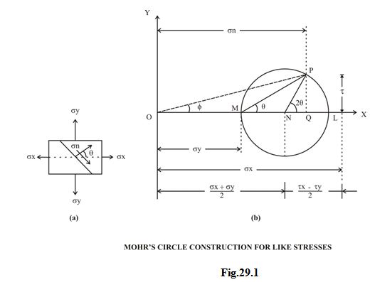
Using some suitable scales, measure OL and OM equal to σx and σy respectively on the axis OX.
Bisect LM at N.
With N as centre and NL or NM radius, draw a circle.
At the centre N draw a line NP at an angle 2Ө, in the same direction as the normal to the plane makes with the direction of σx. In Fig.1 which represents the stress system, the normal to the plane makes an angle Ө with the direction of σx in the anticlockwise direction. The line NP therefore, is drawn in the anticlockwise direction.
From P, draw a perpendicular PQ on the axis OX. PQ will represent τ and OQ σn.
Now, from stress diagram
NP = NL = \[{{{\sigma _{x - {\sigma _y}}}} \over 2}\]
PQ = NP sin2Ө = \[{{{\sigma _{x - {\sigma _y}}}} \over 2}\] sin2Ө = τ ----------------------------------------(8.1)
Similarly, OQ = ON + NQ = \[{{{\sigma _{x + {\sigma _y}}}} \over 2}\] + \[{{{\sigma _{x - {\sigma _y}}}} \over 2}\] cos2Ө = σn--------------(8.2)
Also, from stress circle, τ is maximum when
2Ө = 90°, or Ө = 45°
And, τmax = \[{{{\sigma _{x - {\sigma _y}}}} \over 2}\] ----------------------------------------------------(8.3)
Sign conventions used:
(i) In order to mark τ in stress system, we will take the clockwise shear as positive and anticlockwise shear as negative.
(ii) Positive value of τ will be above the axis and negative values below the axis.
(iii) If Ө is in the anticlockwise direction, the radius vector will be above the axis and Ө will be reckoned positive. If Ө is in the clockwise direction, it will be negative and the radius vector will be below the axis.
(iv) Tensile stress will be reckoned positive and will be plotted to the right of the origin O. Compressive stress will be reckoned negative and will be plotted to the left of the origin O.
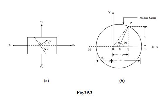
29.1.2 Mohr’s circle construction for ‘Unlike stresses’
In case σx and σy are not like, the same procedure will be followed except that σx and σy will be measured to the opposite sides of the origin. The construction is given in Fig.2.It may be noted that the direction of σn will depend upon its position with respect to the point O. If it is to the right of O, the direction of σn will be the same as that of σx.
29.1.3 Mohr’s circle construction for two perpendicular direct stresses with state of simple shear
Refer to Fig.3. Following steps of construction are followed if the material is subjected to direct stresses σx and σy along with a state of simple shear.
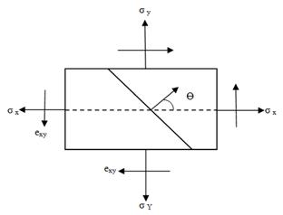
(a)
(b)
Fig.29.3
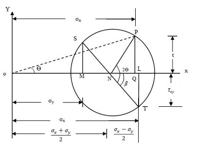
Using some suitable scale, measure OL = σx and OM = σy along the axis OX.
At L draw LT perpendicular to OX and equal to τxy. LT has been drawn downward (as per sign conventions adopted) because τxy is acting up with respect to the plane across which σx is acting, tending to rotate it in the anticlockwise direction and is negative.
Similarly, make MS perpendicular to OX and equal to τxy, but above OX.
Join ST to cut the axis in N.
With N as centre and NS or NT as radius, draw a circle.
At N make NP at angle 2Ө with NT in the anticlockwise direction.
Draw PQ perpendicular to the axis. PQ will give τ while OQ will give σn and OP will give σr.
Proof: Let the radius of the stress circle be R.
Then, R = \[\sqrt {N{L^2} + L{T^2}}\] = \[\sqrt {{{\left[ {{{{\sigma _x} - {\sigma _y}} \over 2}} \right]}^2} + {\tau _{xy}}^2}\]
Also, R cos β = NL = \[{{{\sigma _{x - {\sigma _y}}}} \over 2}\]
R sin β = LT = τxy
Now, OQ = ON + NQ = ON + R cos (2Ө – β)
= ON + R cos 2Ө cos β + R sin 2Ө sin β
= \[{{{\sigma _{x + {\sigma _y}}}} \over 2}\] + \[{{{\sigma _{x - {\sigma _y}}}} \over 2}\] cos2Ө + τxy sin 2Ө (as per eqn-------)
= σn
Similarly,
PQ = R sin (2Ө – β) = R sin2Ө cos β – R cos2Ө sin β
= \[{{{\sigma _{x - {\sigma _y}}}} \over 2}\] sin2Ө – τxy cos 2Ө (as per eqn-------)
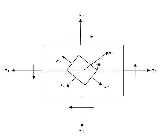
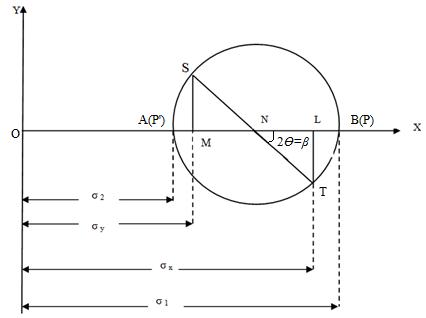
29.1.4 Mohr’s circle construction for principal stresses
Refer to Fig.4.The following are the steps of construction:
(a)
(b)
Fig. 29.4
Mark OL and OM proportional to σx and σy.
At L and M, erect perpendiculars LT = MS proportional to in appropriate directions.
Join ST, intersecting the axis in N.
Since τ = o, NV represents the major principal plane, P coinciding with B. Similarly NPꞌ represents minor principal plane, Pꞌ coinciding with A.
OV = ON + NV = \[{{{\sigma _{x + {\sigma _y}}}} \over 2}\] + R, where R is the radius of the circle.
= \[{{{\sigma _{x - {\sigma _y}}}} \over 2}\] + \[\sqrt {{{\left[ {{{{\sigma _x} - {\sigma _y}} \over 2}} \right]}^2} + {\tau _{xy}}^2}\] = σ1
Similarly, OU = ON – NU
= \[{{{\sigma _{x + {\sigma _y}}}} \over 2}\] - \[\sqrt {{{\left[ {{{{\sigma _x} - {\sigma _y}} \over 2}} \right]}^2} + {\tau _{xy}}^2}\] = σ2
tan β =\[\frac{{LT}}{{LN}}\] = \[\frac{{\tau xy}}{{\frac{{{\sigma _x} - {\sigma _y}}}{2}}}\]
= \[{{2\tau xy} \over {{\sigma _x} - {\sigma _y}}}\] = tan 2Ө (where β = 2Ө)
Last modified: Wednesday, 11 September 2013, 10:39 AM