Site pages
Current course
Participants
General
Module 1. Hydraulic Basics
Module 2. Hydraulic Systems
MODULE 3.
MODULE 4.
MODULE 5.
MODULE 6.
MODULE 7.
MODULE 8.
19 April - 25 April
26 April - 2 May
LESSON 2. HYDRAULIC BASICS
2.1 INTRODUCTION
Transmission of motion can be done easily with liquids. Consider a simple hydraulic device used for lifting a load as shown in Fig. 2.1. It consists of an L-shaped cylinder filled with hydraulic oil and fitted with two pistons at the two extremes. The pistons can move in the cylinder. Piston ‘A’ is used for applying force and piston ‘B’ is used for lifting a load. Piston A is called the apply piston and piston B is called the output piston.
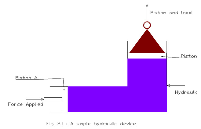
In a hydraulic device power is transmitted by pushing on a confined liquid. The transfer of energy takes place because the confined liquid is subjected to pressure due to the push. This pressure acts equally in all directions. Therefore, when apply piston ‘A’ is pushed towards right a pressure is created in the hydraulic oil, which acts throughout the system equally in all directions. This results in a force on output piston ‘B’ equal to pressure multiplied by area of the piston ‘B’.
For example if a pressure ‘P’ = 20 kgf/cm2 is acting on output piston having area ‘Ap’ = 10 cm2, then the force ‘F’ acting on the piston is calculated as:
F = P x Ap = 20 kgf/cm2 x 10 cm2 = 200 kgf.
Due to this force, the piston ‘B’ will move in upward direction along with the load. The displacement and speed of the output piston will depend upon a number of factors such as combined mass of piston ‘B’ and load, dimensions of cylinder and pistons, fluid characteristics etc. A hydraulic engineer may require to calculate the output piston displacement for a given force on the apply piston or calculate the force required on apply piston for desired displacement of the output piston. For this purpose familiarity with various physical units of fluid power is essential.
2.2 Physical Units for Fluid Power
Hydraulic engineers are concerned with the following three fundamental units:
(a) Length
(b) Mass
(c) Time
Other units such as area, volume, velocity, force and pressure etc. can be defined in terms of the above mentioned fundamental units.
The fundamental units used in hydraulics are measured in various systems of units. British Imperial System also known as FPS system uses foot, pound and second. Metric system uses centimetre, gram and second (the CGS system) or metre, kilogram and second (the MKS system). The MKS system has evolved into SI system which uses is a logical method for defining derived units such as force and pressure, as compared to MKS system.
Now, we will discuss the fundamental and derived units which are significant for understanding hydraulics.
The unit of length is foot (ft) in FPS system, centimetre (cm) in CGS system and metre (m) in MKS and SI systems.
The unit of time is second (s) in CGS, MKS, SI and FPS systems.
Mass is the quantity of matter contained in a body. It’s unit is pound (lb) in FPS system, gram (gm) in CGS system and kilogram (kg) in MKS and SI systems. Mass of a body is always a constant, irrespective of the location where it is measured.
Weight of an object is the force due to gravitational attraction between the object and the earth. Thus weight of an object is a force which is not constant for the object. It’s value depends upon the force of gravity at the location where weight is measured. Thus the weight of an object will be different on the moon than on earth, but the mass of the same object will be same on moon and earth.
When a force ‘F’ is applied to a body having mass ‘m’, acceleration ‘a’ (or deceleration) is produced in the body, given by Newton’s second law of motion:
F = ma (2.1)
The unit of force is pound-force (lb-f) in FPS system, dyne in CGS system, kilogram-force (kg-f) in MKS system and Newton (N) in SI system.
A Newton is defined as the force which produces an acceleration of 1 ms-2 when applied to a mass of 1 kg. Here, it may be noted that the value of acceleration due to gravity is taken as 9.81 ms-2 i.e. 1 g = 9.81 ms-2.
However, when force is taken in lb-f and mass in lb in the relation (2.1), acceleration is measured in g. Thus if a force of 10 lb-f acts on a body having mass of 5 lb, an acceleration equal to 2 g is produced in it.
Similarly, when force is taken in kg-f and mass in kg in the relation (2.1), acceleration is measured in g. Thus if a force of 10 kg-f acts on a body having mass of 5 kg, an acceleration equal to 2 g is produced in it.
Pressure is defined as the normal force acting per unit area. In FPS system the unit of pressure is pound-force per square inch (psi). In metric system, the unit of pressure is taken as kilogram-force per square centimeter (kg-f/cm2).
The SI system defines pressure as the force in Newton per square metre (Nm-2). Further 1 Nm-2 is called 1 Pascal (Pa). One Pascal of pressure quantifies a very low pressure from practical point of view. Therefore kilo Pascal (kPa i.e. 103 Pa) or mega Pascal (MPa i.e. 106 Pa) are more commonly used.
Pressure is exerted due to weight of a fluid. This is usually called pressure head and depends upon height ‘h’ of the fluid. In FPS and metric systems, head (P) is given by:
P = wh (2.2)
where head ‘P’ is measured in psi or kg-f/cm2, ‘w’ is the specific weight of the fluid.
In SI system, expression (2.2) is written as:
P = ρgh (2.3)
where ‘g’ is acceleration due to gravity (9.81 ms-2). The head ‘P’ is measured in Pascal, ‘ρ’ is the density of the fluid and ‘g’ is the acceleration due to gravity.
Pressure in a fluid can also be defined in terms of equivalent head pressure. Common units are millimeter of Mercury (mm of Hg) and centimetre, inches, feet or metre of water.
Pressure is generally measured either with reference to atmospheric pressure or vacuum. When atmospheric pressure is used as reference, the measured pressure is called gauge pressure. When vacuum is used as reference, the measured pressure is called absolute pressure.
2.3 Conversion between Units
The conversion between units for various fundamental and derived quantities is given in Table 2.1.
Table 2.1 Conversion between Units
|
Mass |
|
1 kg = 1000 gm
|
|
Length |
|
1 m = 100 cm = 1000 mm
|
|
Volume |
|
1 litre = 1000 ml
|
|
Force |
|
1 N = 105 dynes
|
|
Pressure |
|
1 bar = 100 kPa = 0.9872 atm (atmosphere) = 750 mm Hg
1 atm = 1.013 x 10⁵ Pa = 1.013 bar
|
2.4 A Hydraulic System
The physical components and their layout for a typical hydraulic system are shown in Fig. 2.2. The basic components are pump, strainer, oil reservoir, filter, pressure gauge, pressure relief valve, control valves, actuator (cylinder or motor) etc. These components are joined together by means of pipes, tubes or hoses.
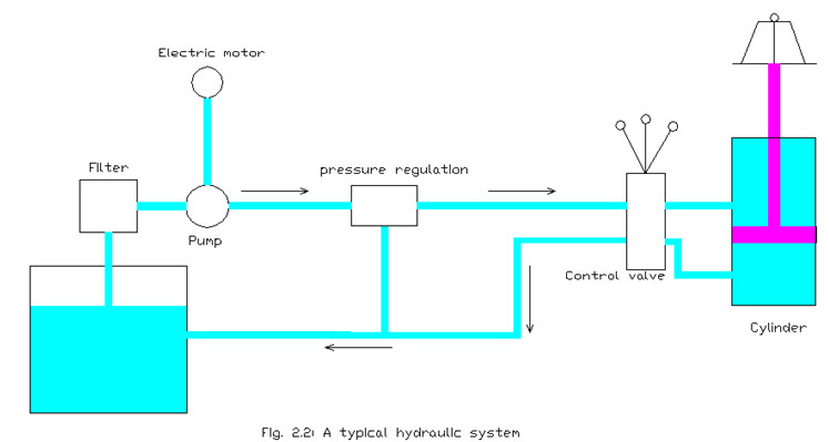
Hydraulic pump
It converts the mechanical energy into hydraulic energy by forcing hydraulic fluid, under pressure, from the reservoir into the system. It may be called heart of the hydraulic system. The pumps used in the hydraulic circuit are generally of three types - piston type, gear type or vane type. A pump normally creates a partial vacuum, which causes the fluid to move through the pump and hence it keep on moving the fluid in the components.
Electric motor and coupling
These are used for running the hydraulic pump. An electric motor of suitable power rating is fitted as per the size of pump, pressure requirements etc. The pump and motor are connected with the help of a flexible coupling. The coupling absorbs the shocks and slight misalignment between the pump and the motor.
Oil sump or reservoir
It acts as a storehouse for the fluid and a heat dissipater. The hydraulic fluid stored in the sump is pumped into various components of the hydraulic system with the help of a pump. The capacity of the sump should be kept large, around three to four times the pump delivery, so that pump can move the fluid through the components continuously.
Strainer or filter
It filters the hydraulic oil circulating in the system. A strainer is required to have a filter in the system because the same oil is utilized again and again which makes the oil contaminated. The filters can be placed in the pump line, pressure line or return line. It collects the particles and prevents them from recirculation in the circuit.
Pressure gauge
It is used for measuring pressure in the hydraulic system. System pressure is required to be measured at the outlet of the pump and hence a pressure gauge is mounted. It indicates the pressure in the lines which is an indicator of the safe working of the system. The pressure gauge may be of dial type or digital type.
Relief valve
It is used to protect the system from damage by releasing excess pressure in the system. Pressure relief valve limits the pressure of the circuit. As the system pressure exceeds the set operating pressure, the relief valve discharges oil directly to return line thereby protecting the system from any damage.
Hydraulic valves
These are provided to control pressure, direction and flow rate of the fluid in the hydraulic system.
Fluid lines
These transport the fluid to and from the pump through the hydraulic system. These lines can be rigid metal tubes, or flexible hose assemblies. Fluid lines can transport fluid under pressure or vacuum (suction).
Fluid
It can be almost any liquid. The most common hydraulic fluids contain specially compounded petroleum oils that lubricate and protect the system from corrosion.
Actuators
It convert hydraulic energy into mechanical energy to do work. A linear actuator gives force and motion outputs in a straight line. It is more commonly called a cylinder. A rotary actuator produces rotational motion like an electric motor.
Last modified: Friday, 14 March 2014, 10:41 AM