Site pages
Current course
Participants
General
MODULE 1.
MODULE 2.
MODULE 3.
MODULE 4.
MODULE 5.
MODULE 6.
MODULE 7.
MODULE 8.
MODULE 9.
MODULE 10.
LESSON 2. ENGINEERING MATERIALS
2.1 Selection of Material
Material selection is a very vital step in the process of machine design. Selection of material depends upon following aspects:
-
Performance Requirements: Material is selected considering the design constraints and performance requirements e.g. loads acting on the member, size & weight constraints, environmental conditions, desired reliability & durability etc.
-
Material Properties: Performance requirements are compared with properties of materials to select the best suitable material. For example stress level estimated for any machine member is compared with the strength of the available materials. Properties can be Physical (melting point, co-efficient of thermal expansion, thermal conductivity, specific heat, specific gravity, electrical conductivity, magnetic properties etc.), Chemical (corrosion resistance, reactivity with acids, bases, water etc.), Mechanical (hardness, toughness, ductility, malleability etc.) or Manufacturing (castability, weldability, formability, machineability etc.). Any of these properties can become important depending upon the design requirements and environmental conditions.
-
Manufacturing Aspects: Along with the selection of material designer also has to decide about the manufacturing processes to be used to give it desired shape. Therefore in addition to the manufacturing properties of the material, manufacturing constraints are also to be taken care of, while selecting a particular material.
-
Availability & Cost: Material selected should be easily available at an acceptable cost. In addition to the material cost, total cost of fabrication is also considered as the desired shape has to be given to the material with best quality and least cost.
Availability of a large number of materials with varying properties makes the job of material selection very difficult. Also due to dynamic nature of the market, cost keeps on varying, desiring the designer to remain updated about the available materials and their cost.
2.2 Stress-Strain Curve
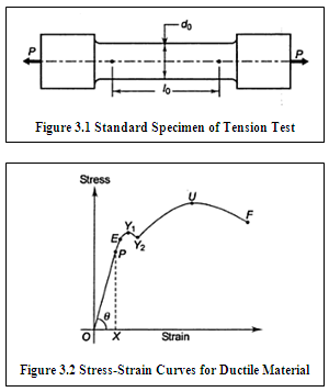
As discussed above, to design any component performance requirements are compared with the properties of the material. These properties are obtained experimentally. Tension test is the simplest and basic test that gives very important properties related to the mechanical behavior of the material. In this test, a standard specimen, shown in Figure 3.1, is subjected to gradually increasing axial tensile force. Before starting the test gauge length is marked on the specimen and initial diameter (\[{d_0}\]) and gauge length (\[{l_0}\]) are measured. Axial tensile load is applied on the specimen, which is increased gradually till the fracture of the component takes place. Load and deformation values are measured and stress (=Force/Area) & strain (=Deformation/Original Length) are calculated at each step. This data is then plotted in the form of stress-strain curve. Typical Stress-Strain curve for ductile material is shown in Figure 3.2. Stress-Strain curve provides the following information:
Proportional Limit (P): Stress-strain curve is linear upto point P and Hook’s Law (Stress \[ \propto\] Strain) is obeyed in region OP. Proportional Limit (P) is the stress at which the stress-strain curve begins to deviate from the straight line.
Modulus of Elasticity: It is the ratio of stress to strain upto point P and is given by slope of line OP. \[{\text{YoungsModulus}},E = tan\theta= PX/OX = stress/strain\] .
Elastic Limit: Upto point E, when the load is removed, specimen regains its original size and shape i.e. it remains in the elastic stage upto point E (elastic limit). The elastic limit is the maximum stress without any permanent deformation. If the specimen is loaded beyond this point, plastic deformation takes place and the material takes a permanent set when the load is removed. Proportional Limit (P) and Elastic Limit (E) are very close to each other and are often taken to be equal.
Yield Strength (\[{S_{yt}}\]) : Point on the stress-strain curve at which the strain begins to increase very rapidly without a corresponding increase in stress is called yield point. Yield Strength is the maximum stress at which a marked increase in elongation occurs without increase in load. All materials don’t have a well defined yield point. In such cases, Yield Strength is defined as the stress corresponding to a permanent set of 0.2% of gauge length and is determined with the help of offset method by drawing a line parallel to OP passing through A, with OA=0.002 mm/mm strain, which intersects with stress-strain curve at Y, called the Yield Point and corresponding stress is called 0.2% Yield Strength. Proof Strength is also similar to Yield Strength with offset of 0.001 mm/mm, called as 0.1% Proof Strength.
Ultimate Tensile Strength (\[{S_{ut}}\]) : As the material begins to deform plastically, it becomes stronger due to strain hardening and higher and higher load is required for its deformation, leading to increase in the stress and after point U, it begins to fall. Ultimate tensile strength is the maximum stress reached in the stress-strain curve, corresponding to point U.
Breaking Strength: After U, the cross-sectional area of specimen begins to decrease rapidly and a localized decrease in area called ‘necking’ takes place and ultimately the fracture takes place. F is called Fracture Point and corresponding stress is called Breaking Strengh.
Percentage Elongation: It is the ratio of increase in the gauge length of the specimen, at the time of fracture, to its original length, expressed in percent. It is a measure of ductility of the material and is given by, \[PercentageElongation = \left( {l - {l_0}} \right)/{l_0} \times 100\]
Percentage Reduction in Area: It is the ratio of decrease in cross-sectional area of the specimen after fracture to the original cross-sectional area, expressed in percent. It also is a measure of ductility and is given by, \[PercentageReductioninArea = \left( {{A_0} - A} \right)/{A_0} \times 100\]
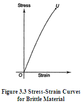
Brittle Materials don’t exhibit Yield Point, deviation of stress-strain curve from straight line begins very early, there is very small plastic deformation, no necking occurs and fracture takes place suddenly. Stress-strain curve for a brittle material is shown in Figure 3.3.
2.3 Mechanical Properties of Materials
Mechanical properties of materials describe their behavior under the action of external forces and are very important in the determination of shape and size of the components. Following are some important mechanical properties:
|
Strength |
Ability of the material to withstand external forces without yielding or fracture. |
|
Stiffness |
Ability of the material to resist deformation under the action of external forces. |
|
Elasticity |
Ability of the material to regain its original shape and size when the external load is removed. |
|
Plasticity |
Ability of the material to permanently retain the deformation produced due to external load. Ability to have large plastic deformation without fracture is very important property in certain operations like stamping. |
|
Ductility |
Ability of the material to have large plastic deformation without fracture when subjected to tensile force. It is measured by %age elongation and %age reduction in area. Ductility decreases with increase in temperature. |
|
Malleability |
Ability of the material to have large plastic deformation without fracture when subjected to compressive force. Malleability increases with increase in temperature. |
|
Brittleness |
Property of the material to show negligible plastic deformation before fracture. |
|
Hardness |
Ability of the material to resist penetration, plastic indentation, abrasion or scratching. Wear resistance increases with increase in hardness and processes like case hardening are used to increase to increase the hardness of surfaces rubbing against each other. |
|
Resiliance |
Ability of the material to absorb energy when deformed elastically and release this energy when unloaded. It is measured by Modulus of Resiliance which is strain energy per unit volume upto the elastic limit and is given by the area under the stress-strain curve, from origin to elastic limit. |
|
Toughness |
Ability of the material to absorb energy before the fracture takes place. Tough materials have ability to bend, twist or stretch before it gets fractured. It is an important property for components subjected to shock loads. It is measured by Modulus of Toughness which is the total work done or energy absorbed by the component upto the fracture point and is given by the area under the stress-strain curve upto the fracture point. |
2.4 Engineering Materials
Engineering Materials can be classified as metals (ferrous & non-ferrous) and non-metals, which are discussed in the following articles:
2.4.1 Ferrous Materials
Ferrous materials can be classified into Wrought Iron, Cast Iron and Steel.
2.4.1.1 Wrought Iron and Cast Iron
Wrought Iron and Cast Iron along with its types are discussed in the table given below
|
|
Introduction |
Properties |
Applications |
|
Wrought Iron |
Purest form of iron with more than 99.5% Fe |
Tough, malleable, ductile, weldable, forgeable & corrosion resistant Poor castability, high melting point (1510°C)low impact strength, cannot be hardened or tempered |
Bolts, nuts, railway couplings, chains, crain hooks, oil rigs, pipes, pipe fittings, plates, sheets etc. |
|
Cast Iron |
An alloy of Fe & C with C > 2%, other ingradients – Si, Mn, S, Ph etc, hard and brittle |
Low cost, good castability & machinability, high compressive strength, wear resistant, good vibration damping capacity Very brittle, low plasticity, low malleability, cannot be forged |
Automobile engine blocks, machine tool structures |
|
Grey Cast Iron |
Contains 2.5 to 3.75 % C present in the form of graphite flakes, giving gray color and hence its name. Examples: FG150, FG250, FG350Si12 (no. indicates UTS, Si12 means 12% Si) |
Low cost, good castability & machinability, high compressive strength, graphite acts as lubricant making it suitable for sliding parts Low tensile and impact strength, less ductility, poor weldability |
Machine tool structures, gas/ water pipeselectric motor frames, piston rings, flywheels, cylinder block, heads, housings |
|
White Cast Iron |
Contains 1.75 to 2.30% C present in the form of cementite (Fe3C) |
Very hard and brittle, good abrasion resistance, poor mechanical properties, low machinability |
Rail/car wheels, valve seats, cams, small pulleys, rollers, gears |
|
Malleable Cast Iron |
Obtained by annealing of white cast iron, contains 2.2 to 3.6% C. Examples: BM 300 WM200 PM400 BM, WM & PM indicate Black hearth, White hearth & Pearlitic Malleable CI resp. numbers indicate UTS |
Low cost, malleable, ductile, forgeable, good wear resistance, impact strength and vibration damping capaity |
Crank case, pump bodies, conveyer chain links, crankshafts, levers etc. |
|
Spheroidal Cast Iron |
Also known as nodular or ductile CI, C (graphite) is present in the spheroidal/nodular form |
Stronger, more ductile, tougher, good fluidity, castability, machinabilty, weldability and wear resistance |
Cylinders, cylinder heads, valves, pipes, pipe fittings, power transmission equipment, earth moving machinery |
|
Alloy Cast Iron |
Improved properties by adding alloying elements like Ni, Cr, Mo, Cu, Si, Mn etc. |
Increased strength, high wear and corrosion resistance |
Automobile parts like cylinders, pistons, piston rings, crank case, brake drums, crushing and grinding machine parts |
2.4.1.2 Steel
It is an alloy of Fe and C with C < 1.5%. C is present in the form of iron carbide (Fe3C), which imparts hardness and strength. No free carbon (graphite) is present. Steel is used for most of the engineering applications. Its properties can be modified using heat treatment. It can be classified as Plain Carbon Steels and Alloy Steels.
Plain Carbon Steel: It contains 0.5 to 1.0 % of C. It is cheap, easily available, has wide range of mechanical properties that can be controlled with the help of heat treatment and alloying elements, has good machinability and weldability. It can be classified as low, medium and high carbon steel.
|
Type |
Carbon %age |
Properties |
Applications |
|
Low Carbon Steel (Mild Steel) |
< 0.3 % |
Very soft and ductile, good machinability and weldability |
Small forgings, machined, welded and cold formed parts |
|
Medium Carbon Steel |
0.3 to 0.7 % |
High strength , good weldability |
Most machine components |
|
High Carbon Steel |
> 0.7 % |
High yield strength, tough, hard and brittle, low weldability |
Cutting tools, springs, bearings |
Alloy Steels: When certain alloying elements are added in sufficient quantity to impart some desired property, these are called alloy steels. For example, Ni provides hardness, strength & toughness without compromising ductility, Cr provides high hardness, strength, wear & corrosion resistance, Mo & W increases hardenabilty & wear resistance, V improves fatigue resistance and so on. Some examples of alloy steels are 40Cr1Mo28, 40Ni3, 37Mn2, 31Ni3Cr65Mo55.Table gives the list of some alloying elements along with the properties they impart.
2.4.2 Non-ferrous Materials
A variety of non-ferrous materials are also used in engineering applications. They are soft, have low melting point, low strength, high corrosion resistance, can be cold worked and have good manufacturing properties. Some important non-ferrous materials are Al Alloys (Duralumin, Y alloy, Magnalium, Hindalium), Cu Alloys (Brasses, Bronzes, Gun metal, Babbits), Ni Alloys (Monel Metal, Inconel, Nichrome, Nimonics) etc.
2.4.3 Non-Metallic Materials
Non-metals have low cost, flexibility and resistance to heat & electricity. Examples are timber, leather, rubber, plastics etc.
References
-
Design of Machine Elements by VB Bhandari
-
Mechanical Engineering Design by J.E. Shigley
-
Analysis and Design of Machine Elements by V.K. Jadon
-
Design of Machine Elements by C.S. Sharma & K. Purohit
-
Manufacturing Processes by U.K. Singh & M. Dwiwedi
Last modified: Wednesday, 19 March 2014, 5:12 AM