


Site pages
Current course
Participants
General
MODULE 1.
MODULE 2.
MODULE 3.
MODULE 4.
MODULE 5.
MODULE 6.
MODULE 7.
MODULE 8.
MODULE 9.
MODULE 10.
LESSON 17 SPRINGS
17.1 Introduction
Mechanical spring is an elastic member whose primary function is to deflect under load and to recover its original shape and position when load is released. Springs are used to absorb shocks and vibrations (e.g. vehicle suspension system), store energy (e.g. springs n clocks and toys), measure force (e.g. spring balance) and to apply force and control motion (e.g. cam and follower).
17.2 Types of Springs
Springs are classified based on their shape. Some of the important types of springs are as follows:
17.2.1 Helical Springs
|
Figure 17.1 Helical Spring |
The helical springs are made from a wire coiled in the form of a helix as shown in Figure 1. Cross-section of the wire is generally circular and it can be square or rectangular also. Helical springs are easy to manufacture, reliable and have a constant spring rate i.e spring deflection is directly proportional to the force acting. These are of two types – compression helical springs and tension helical springs. Compression helical springs are designed to take compressive loads and they get compressed under the loading and the tension helical springs are designed to take tensile loads and they get elongated under the external loads. The load acts along the axes of these springs. In helical sprigs, the wire is subjected to torsional shear stress.
Helical springs are also classified as closely-coiled and open-coiled springs. In closely-coiled springs, wire is coiled so close that the plane containing each turn is nearly at right angles to the axis of the helix i.e. the helix angle is very small, usually less than 10°. In open-coiled helical springs, the wire is so coiled that there is a gap between the two consecutive turns i.e. the helix angle is large.
17.2.2 Conical Springs
Conical spring works in compression and is used where variable spring rate is required. Wire is coiled in the form of a cone as shown in Figure 17.2.
|
Figure 17.3 Torsion Spring |
|
Figure 17.2 Conical Spring |
17.2.3 Torsion Springs
Torsion springs are of two types - helical and spiral. These springs are loaded in torsion and the load tends to wind up the spring. Wire is subjected to bending moment in this case. Torsion springs are shown in Figure17.3.
17.2.4 Leaf or Laminated Springs
|
Figure 17.5 Belleville Spring |
|
Figure 17.4 Leaf Spring |
The laminated or leaf spring consists of a number of flat plates (known as leaves), usually of semi-elliptical shape, of varying lengths held together by means of clamps and bolts. These are mostly used in automobiles. A typical leaf spring is shown in Figure 17.4.
17.2.5 Disc or Belleville Springs
These springs consists of a number of conical discs held together as shown in Figure 17.4. Belleville springs have high spring rate and are compact.
17.3 Spring Materials
Spring materials should have high yield strength and low modulus of elasticity so that they don’t permanently deform under the applied loads. Springs are made of the materials that can be formed (rolled or drawn) to high strength and retain enough ductility to form or the alloys that can be heat treated to high strength and ductility before or after forming. Both hot and cold working processes are used for manufacturing springs. The selection of process depends upon size of material, spring index and the properties desired. Winding of the spring induces residual stresses due to bending, which are released with the help of heat treatment. Materials used for springs are plain carbon steels, alloy steels and also the non-ferrous materials like phosphor bronzes, spring brass, beryllium copper and various nickel alloys.
17.4 Terminology of Helical Springs
Figure 17.6 shows a helical spring subjected to compressive force, W.
|
Figure 17.6 Compression Helical Spring |
Solid Length: Length of the spring when it is compressed so that the coils touch each other.
Solid Length , Ls = n.d
where n = numbers of coils and d = wire diameter
Compressed Length: Length of the spring, when it is subjected to maximum compressive force.
Even under the worst load, minimum clearance is maintained between the two adjacent coils so that they don’t clash with each other. It is called clash allowance and is generally taken as 15% of the maximum deflection.
Free Length: Length of the spring in the free or unloaded condition.

Spring Index: Ratio of the mean diameter of the coil to the diameter of the wire .
![]()
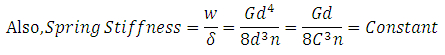
Spring Rate/Spring Stiffness/Spring Constant: Force required to produce unit deflection in the spring.
Spring Rate , k = W / σ where, and .
Pitch of the Coil: Axial distance between adjacent coils of the spring in uncompressed state.
Pitch of the Coil = p = Free Length / (n - 1)
17.5 Design of Helical Springs
17.5.1 Stress in Helical Springs
Under the compressive load, W acting on the spring, coil of the spring is subjected to two types of stresses – direct shear stress and torsional shear stress due to twisting of the coil.
Torque = T = W . D / 2
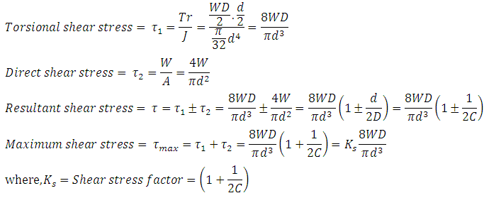
In the analysis above effect of stress concentration is not considered. AM Wahl introduced a factor called Wahl’s Stress Factor, K that takes care of stress concentration also along with the shear stress.
According to Wahl, Maximum shear stress is given by,
Maximum shear stress = ![]()
Wahl’s Factor is given by,
Wahl’s Factor , ![]()
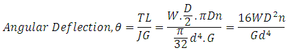
17.5.2 Deflection in Helical Springs
![]()
If J is polar moment of inertia and G is Modulus of Rigidity of coil, angular deflection of the wire due to twisting is given by,
References
-
Design of Machine Elements by VB Bhandari
-
Mechanical Engineering Design by J.E. Shigley
-
Analysis and Design of Machine Elements by V.K. Jadon
-
Machine Design by R.S. Khurmi
-
5. Design of Machine Elements by C.S. Sharma & K. Purohit
Last modified: Thursday, 20 March 2014, 10:11 AM