Site pages
Current course
Participants
General
Module 1. Introduction to Theory of Machine
Module 2. Planar Mechanism
Module 3. Velocity and Acceleration Analysis
15 March - 21 March
22 March - 28 March
29 March - 4 April
5 April - 11 April
12 April - 18 April
19 April - 25 April
26 April - 2 May
Lesson 3. Degree of Freedom
3.1 DEGREE OF FREEDOM
An object in space has six degrees of freedom.
Translatory motion along X, Y, and Z axis (3 D.O.F.)
Rotary motion about X, Y, and Z axis (3 D.O.F)

Fig.2.6 Degree of freedom
The rigid body has 6 DOF in space but due to formation of linkage one or more DOF is lost due to the presence of constraint on the body. The total number constraints cannot be zero as the body has to be fixed at some place to make the linkage possible. Thus the degree of freedom is given by
DOF= 6- (Numbers of Restraints)
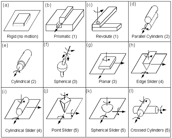
Fig.2.7 Pairs having varying degree of freedom
|
S. No. |
Geometrical Shapes involved |
Restraints on |
Degree of freedom |
Total restraints |
|
|
Translatory motion |
Rotary motion |
|
|
||
|
(a) |
Rigid |
0 |
0 |
0 |
6 |
|
(b) |
Prismatic |
2 |
3 |
1 |
5 |
|
(c) |
Revolute |
3 |
2 |
1 |
5 |
|
(d) |
Parallel cylinders |
2 |
2 |
2 |
4 |
|
(e) |
Cylindrical |
2 |
2 |
2 |
4 |
|
(f) |
Spherical |
3 |
0 |
3 |
3 |
|
(g) |
Planer |
1 |
2 |
3 |
3 |
|
(h) |
Edge slider |
1 |
1 |
4 |
2 |
|
(i) |
Cylindrical slider |
1 |
1 |
4 |
2 |
|
(j) |
Point slider |
1 |
0 |
5 |
1 |
|
(k) |
Spherical slider |
1 |
0 |
5 |
1 |
|
(l) |
Crossed cylinder |
1 |
0 |
5 |
1 |
Table 2.1
|
Figure |
Explanation for DOF |
|
2.9 a |
(0) As there is no motion hence DOF is zero |
|
2.9 b |
(1) As movement is possible only in Z direction. |
|
2.9 c |
(1) As it can revolve around Y axis |
|
2.9 d |
(2) As one element can move in Z axis & also revolve around Z axis |
|
2.9 e |
(2) As element inside can revolve around Z axis and also move in Z axis |
|
2.9 f |
(3) As element can revolve around X,Y&Z axis |
|
2.9 g |
(3) As element can revolve around Y axis & can move in Z & X axis |
|
2.9 h |
(4) As element can revolve around Z & Y axis & can move in Y axis |
|
2.9 i |
(4) As element can revolve around Z & Y axis & can move in Z & X axis |
|
2.9 j |
(5) As an element can revolve around X,Y&Z axis & can move in X & Z axis |
|
2.9 k |
(5) As element can revolve around X,Y & Z axis & can move in X & Z axis |
|
2.9 l |
(5) As element can revolve around X,Y & Z axis & can move in X & Z axis |
Table 2.2
3.2. KINEMATIC CHAIN
a) Kinematic chain: A kinematic chain is an assembly of links which are interconnected through joints or pairs, in which the relative motions between the links is possible and the motion of each link relative to the other is definite.
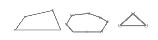
a. kinematic chain b. non kinematic chain c. redundant chain
Fig.2.8 kinematic chains
b) Non-kinematic chain: In case the motion of a link results in indefinite motions of others links, it is a non-kinematic chain. The reason for this indefinite motion lies in the fact that if we give motion to any of the link in the chain then the other links can take indefinite position.
c) Redundant chain: There is no motion possible in the redundant chain. It can be observed from the figure 2.9 c that this chain is locked due to its geometry.
3.3 DEGREE OF FREEDOM IN A MECHANISM
Degrees of freedom of a mechanism in space can be explained as follows:
Let
N = total number of links in a mechanism
F = degrees of freedom
J1 = number of pairs having one degree of freedom
J2 = number of pairs having two degree of freedom and so on.
When one of the links is fixed in a mechanism
Then, the number of the movable links are = N - 1
Degrees of freedom of (N- 1) movable links = 6(N-1)
(Because each movable link has six degree of freedom) Each pair having one degree of freedom imposes 5 restraints on the mechanism reducing its degrees of freedom by 5J1 this is because of the fact that the restraint on any of the link is common to the mechanism as well. Other pairs having 2, 3, 4 and 5 degrees of freedom reduce the degree of freedom of the mechanism by putting constraints on the mechanism as well.
Then, the DOF can be given by
F = 6(N-1) - 5J1 - 4J2 - 3J3 - 2J4 - 1J5
Most of the mechanism we generally study are two dimensional in nature, such as slider-crank mechanism in which translatory motion is possible along two axes(one restraint) and rotary motion about only one axis(two restraints).Thus there are three general restraints in a two dimensional mechanism. This can be shown with the help of figure 2.10 that a link has three degree of freedom in two dimensions.
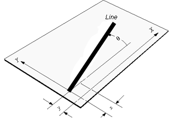
Fig.2.9 a line in a plane has three DOF: x, y, θ
Therefore, for plane mechanism, the following relation can be used for degrees of freedom,
F = 3 (N-1) - 2J1 - 1J2
This equation is known as Gruebler’s criterion for degrees of freedom of plane mechanism. It should be noted here that gruebler’s criterion does not take care of geometry of the mechanism so it can give wrong prediction. So, inspection should be done in certain cases to find the degrees of freedom.
Example: 2.1 Find the degree of freedom of the mechanism given below.
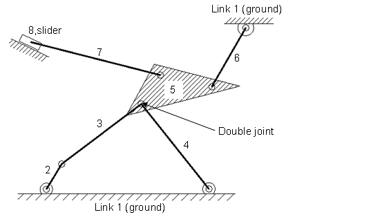
Fig.2.10
Solution:
Number of links=8
Numbers pairs having one degrees of freedom=10 by counting
How to calculate pairs
Pair 1 Link 1 (ground) and link 2 constitute a single turning pair
Pair 2 Link 2 and link 3 constitute a single turning pair
Pair 3 Link 3 and link 5 constitute a single turning pair
Pair 4 Link 4 and link 5 constitute a single turning pair
Pair 5 Link 5 and link 6 constitute a single turning pair
Pair 6 Link 6 and ground (link 1) constitute a turning pair
Pair 7 Link 5 and link 7 constitute a turning pair
Pair 8 Link 7 and link 8 constitute a turning pair
Pair 9 Link 8 and ground (link 1) constitute a sliding pair
Pair 10 Link 4 and ground (link 1) constitute a turning pair
As all the pair calculated have one degree of freedom so there is only term J1 is used as it denotes the pair having single degree of freedom.
J1 = 10 (as all pairs have one degree of freedom)
F = 3 (N-1) - 2J1 - 1J2
DOF=3(8-1)-2×10=1
The degree of freedom is one for this mechanism.
Example 2.2 Find the degree of freedom of the mechanism given below.
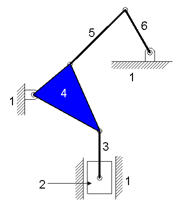
Fig. 2.11
Solution:
Number of links = 6
Number of Pairs = 7
J1 = 7 (six turning pairs and one sliding pair)
DOF=3(6-1)-2×7=1
The degree of freedom is one.
Example 2.3: Find the mobility or degree of freedom of the following mechanism.
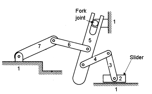
Fig. 2.12
Solution:
Number of links = 7
Number of Pairs = 8
J1 = 7 (six turning pairs and one sliding pair)
J2 = 1 (Fork joint is two DOF joint)
DOF=3(7-1)-2×7-1×1=3
The degree of freedom is one.
Last modified: Tuesday, 25 March 2014, 6:58 AM