Site pages
Current course
Participants
General
Module 1. Introduction to Theory of Machine
Module 2. Planar Mechanism
Module 3. Velocity and Acceleration Analysis
15 March - 21 March
22 March - 28 March
29 March - 4 April
5 April - 11 April
12 April - 18 April
19 April - 25 April
26 April - 2 May
Lesson 4.
4.1 FOUR BAR MECHANISM
The four bar linkage, as shown in figure 2.13 below, is a basic mechanism which is quite common. Further, the vast majority of planar one degree-of-freedom (DOF) mechanisms have "equivalent" four bar mechanisms. The four bar has two rotating links (2 and 4)) which have fixed pivots. One of the levers would be an input rotation, while the other would be the output rotation. The two levers have their fixed pivots with the ground link (1) and are connected by the coupler link (3).
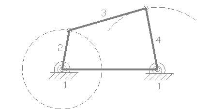 Fig.2.13 four bar mechanism
Crank (2) - a ground pivoted link which is continuously rotatable.
Rocker (4) - a ground pivoted link that is only capable of oscillating between two limit positions and cannot rotate continuously.
Coupler (3) - a link opposite to the fixed link.
1. If the length of any link is greater than the sum of lengths of other three links then it cannot act as four bar linkage.
2. If the sum of the lengths of the largest and the shortest links is less than the sum of the lengths of the other two links, then the linkage is known as a class-1 four bar linkage
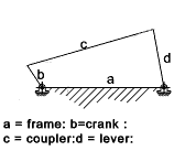 Fig.2.14 crank rocker
In fig 2.14 the links adjacent to the shortest link b is fixed. The mechanism such obtained is known as crank-lever or crank rocker mechanism.
If the shortest link b is fixed, the mechanism obtained is crank-crank or double crank mechanism.
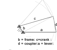
Fig.2.15 double crank
If the link opposite to the shortest link is fixed then the mechanism is know as double-rocker or double lever mechanism.
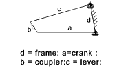
Fig. 2.16 double rocker
4.2 INVERSIONS OF SLIDER CRANK MECHANISM
Different mechanisms are obtained when we fixed different links of a Kinematic chain and the phenomenon is known as inversion of mechanism. A slider crank mechanism has the following inversions.
First Inversion
This inversion is obtained when link 1 is fixed (as shown in fig 2.17) and links 2 and 4 are made the crank and the slider respectively.
Application: This mechanism is commonly used in I.C. engines, steam engines and reciprocating compressor mechanism.
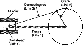 Fig.2.17 reciprocating engine
Second Inversion
By fixing link 2 of a slider mechanism gives second inversion. Rotary engine mechanism or gnome engine is the application of second inversion. It is a rotary cylinder V – type internal combustion engine used as an aero engine. The rotary engine has generally seven cylinders in one plane. The crank (link 2) is fixed and all the connecting rods from the pistons are connected to this link. In this mechanism when the pistons reciprocate in the cylinders, the whole assembly of cylinders, pistons and connecting rods rotate about the axis O, where the entire mechanical power developed, is obtained in the form of rotation of the crank shaft.
Application: Rotary engine mechanism or gnome engine
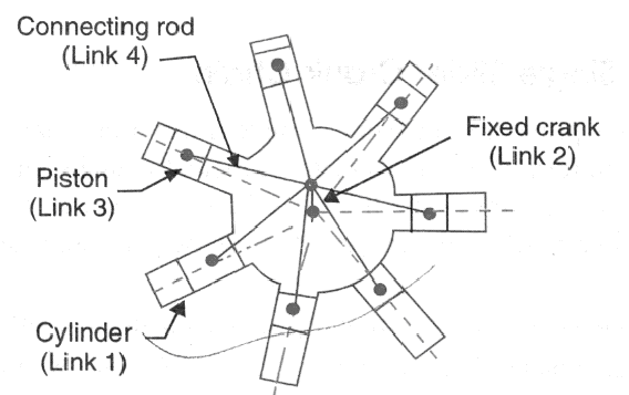
Fig.2.18 rotary engine
Third Inversion
By fixing the link 3(connecting rod) of the slider crank mechanism we can obtain third inversion (as shown in fig.2.19). It is used in hoisting engine mechanism and also in toys. In hoisting purposes, its main advantages lie in its compactness of construction as it allows simple method of supplying steam to the cylinder.
Application: It is used in hoisting engine mechanism and also in toys
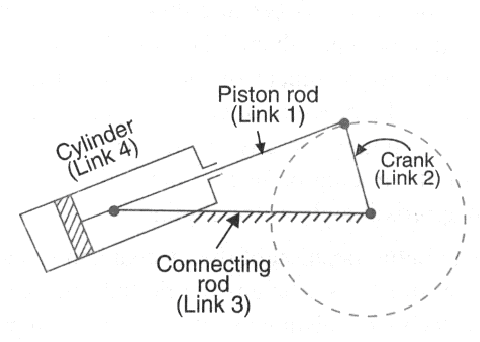
Fig.2.19 oscillating cylinder engine
Fourth Inversion
By fixing the link 4 of the slider crank mechanism we can obtain the fourth inversion of slider crank. Fixing the slider means that the slider should be fixed in position and also should be fixed in respect to rotation. In this case, the cylinder will have to be slotted to give passage to piston pin of connecting rod as the cylinder slides over the piston. Due to this difficulty, the shapes of the cylinder and piston are exchanged as shown in figure below.
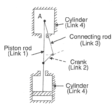
Fig.2.20 pendulum pump
Application: hand pump
Last modified: Tuesday, 25 March 2014, 7:11 AM