Site pages
Current course
Participants
General
Module 1. Tractor Mechanics
Module 2. Traction
Module 3. Introduction to Transmission System
Module 4. Clutch System
Module 5. Gear Box
Module 6. Differential and Final drive
Module 7. Brakes
Module 8. Steering system
Module 9. Hydraulics
Module 10. Power Transmission
Lesson 6. Traction and related definitions, mechanics of a rigid wheel (traction and towed)
A pneumatic tyre which is flexible has a smaller contact area on cocreate surface than it dose on soft ground. A rule of thumb which can be used for estimation of tire contact area is given below-
A = bl
Where:
A = Tire contact area
b = Section width of tire
l = Contact length of tire
experimentally it has found that it is
A = 0.78 bl
Traction testing machine
The traction testing device, is a soil bin based that can be used to conduct controlled experiments.. With this tires of varying diameters widths can be tested. The system is designed will provide variable vertical load up to get varying pull force. The device can be operated in a draft control or a slip control mode.The simplest device for a traction test of a wheeled device requires supporting the moving wheel, which applythe required torque, and measuring the developed force . However, there are variousways by which this can be carried out , with varying levels of complexity. Some devices can be operated only in soilbins, whereas, others are operated in the field.
Tire testing procedure
The tire test consisted of several runs and for a given run, vertical load on the tire is varied to get pull force under controlled slip using load cell type of sensors. The slip control mode may include zero slip to higher slip levels using single wheel tyre tester. In this type of machine torque and speed can also be measured by installing the required sensors to estimate traction performance parameters.
Traction Terminology
Traction.
The process by which a tractor develops tractive force and overcomes motion resistance to produce desired motion.
Tractive force
The force developed on the tractor interface by the traction device as a result of applied torque from the power source.
Motion resistance
Any force imposing resistance against desired motion.
Rolling resistance
Motion resistance that arises from deformations in the soil and the traction device
Sinkage
The depth to which the traction device penetrate into the soil measurednormal to the original, undisturbed surface.
Slip
It is an indication of how the speed of the traction device differs from the forward speed of the tractor. It can be defined as as the percentage travel reduction and given as
S = [ 1 – Va/Vt] 100
Coff
Traction efficiency
The efficiency of the tractive device is converting the axle input power into output power, the term tractive efficiency (TE) has been defined as
TE = Output power/ Input power x100
Basically tractive efficiency is converting the axle torque into net traction .
Traction prediction equation
Dimensional analysis is the best technique used to develop the prediction models for traction forces of pneumatic wheel type of tractor in tillage operation. Soil-wheel interaction was considered in developing the prediction models. Based on the Buckingham Pi Theorem, the number of dimensionless and independent quantities required to fully express the relationship between the variables were determined. Total number of factors can be listed as below table1-
Table 1 : the effective factors of soil and tractor
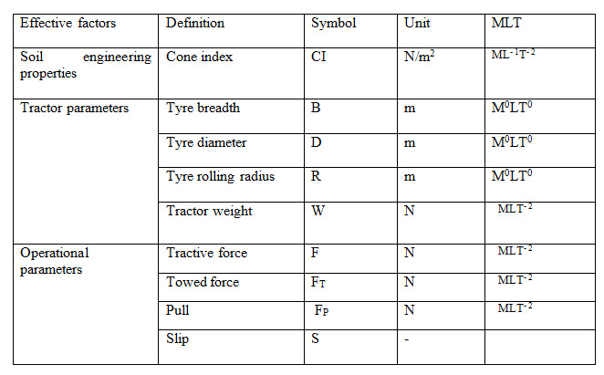
The factors listed above in table 1, can be written as-
F, FT , FP =f ( CI, B, D , R, W, S )
According to Buckingham's theory, the number of invariants and repetitive invariants were 9 and 2 respectively, so 7 constant pi-values are obtained. In this, two repetitive invariants - weight (W) and breadth( B ) are used. Using the dimensional analysis with considering the two repeating variables, the π numbers can be written as –
Π1, Π2, Π3 = f (Π4, Π5, Π6 Π7 )
Equating the exponents of two sides of each π number and by Solving these we obtained an equations for a1, b1, …, , with seven dimensionless parameters in the form as mentioned below-
Π1, = F (W)a1(B )b1 = M0L0T0
Π2, = FT (W)a2(B )b2 = M0L0T0
Π3 = FP (W)a3(B )b3 = M0L0T0
Π4 = CI(W)a4(B )b4 = M0L0T0
Π5 = D (W)a5(B )b5 = M0L0T0
Π6 = R(W)a6(B )b6 = M0L0T0
Π7 = S(W)a7(B )b7 = M0L0T0
The combination of extracted π numbers can be written as a functional equation in the form of:
Π1, = F /W
Π2, = FT /W
Π3 = FP /W
Π4 = B2CI/W
Π5 = D/B
Π6 = R/B
Π7 = S
It can also be written as –
F/W, FT /W, FP /W = B *D* CI/W, D/B, R/B, S
TOWED WHEEL
A towed wheel is an unpowered wheel and axle torque is considered to be zero . The towed force of a towed pneumatic tire is generally dependent upon load, size and inflation pressure, as well as soil strength. Hence the towed force can be predicted from-
FT /W = 1.2 /Cn + 0.o4
Where
FT = towed force of wheel
W= dynamic wheel load
B = unloaded tire width
D = unloaded tire diameter.
Cn= wheel numeric
Cn = B D CI/W
CI = cone index
DRIVING WHEEL
The variations of driving wheel performance is based on the consideration that the normal tire inflation pressures in agricultural tyres produce tire deflections of approximately 20 per cent. Therefore, traction prediction equation can be given as for net pull, slip, and load -
FP /W = 0.75(1- e-CnS) - ( 1.2/Cn + 0.04)
Where,
FP = wheel pull
W = dynamic wheel load
e = base of natural logarithms
Cn = CIBD/W
CI, B,D and S as stated before.
Last modified: Monday, 3 March 2014, 4:33 AM