Site pages
Current course
Participants
General
Module 1. Tractor Mechanics
Module 2. Traction
Module 3. Introduction to Transmission System
Module 4. Clutch System
Module 5. Gear Box
Module 6. Differential and Final drive
Module 7. Brakes
Module 8. Steering system
Module 9. Hydraulics
Module 10. Power Transmission
Lesson 23. Steering system : Necessity. Steering Geometry
Steering System
The steering system is required to control the direction of motion of the vehicle (tractor in our case). This is done through a series of links used to convert the rotation of the steering wheel into change of angle of the axis of the steering wheels. Another function of the steering system is to provide directional stability. The motion of the vehicle being steered needs to become straight ahead when the force on the steering wheel is removed. The design of the steering system should be such that it should cause minimum wear of the tyres of the wheels.
The steering system can be classified into from wheel steering, rear wheel steering or all wheel steering.
The system, governing the angular movement of front wheels of a tractor is called steering system. This system steering wheel minimizes the efforts of the operator in turning the front wheel with the application of leverages. The different components of the system are:
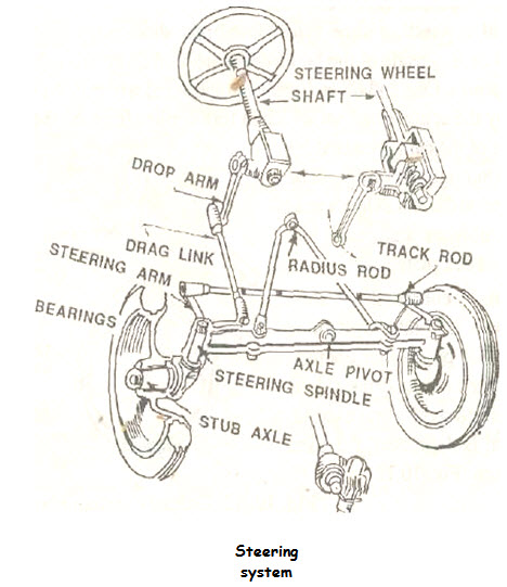
- steering wheel
- steering shaft
- steering gear
- pitman arm (drop arm)
- drag link
- steering arm
- tie rod and
- king pin.
When the operator turns the steering wheel, the motion is transmitted through the steering shaft to tire angular motion of the pitman arm, through a set of gears. The angular movement of the pitman arm is further transmitted to the steering arm through the drag link and tie rods. Steering arms are keyed to the respective king pins which are integral part of the stub axle on which wheels are mounted. The movement of the steering arm affects the angular movement of the front wheel. In another design, instead of one pitman arm and drag link, two pitman arms and drag links are used and the use of tie rod is avoided to connect both steering arms.
TRACTOR TYRE AND FRONT AXLE
The tyres are available in many sizes with the ply ratings as 4, 6 or 8. The ply rating of tyres indicates the comparative strength of tyres. The higher the rating, the stronger are the tyres. The tyres size 12—38 means, that the sectional diameter of tyres is 12" and it is mounted on a rim of 38" diameter. The inflation pressure in the rear wheels of the tractor varies between 0.8 to 1.5 kg/cm2. The inflation pressure of the front wheel varies from 1.5 to 2.5 kg/cm2. Useful life of the pneumatic tyres under normal operating condition may be about 6000 working hours for drawbar work.
FRONT AXLE AND STEERING MECHANISM
Front Axle
The front axles are generally dead axles. The front wheel hubs rotate on anti friction bearing of tapered - roller type on the steering spindle which are an integral part of steering knuckle. To permit the wheels to be turned by the steering gear, the steering spindle and steering knuckle assemblies are hinged at the end of the axle. The pin that forms the pivot of this hinge is known as Kingpin or steering knuckle pin.
FRONT WHEEL ALIGNMENT
The front wheels must be in correct alignment in order to ensure easy steering, to give directional stability of the vehicle and to minimize tyre wear. Front wheel alignment is obtained through accurately setting of the following factors:
- Caster
- Camber
- Kingpin inclination
- Toe-in
- Toe-out
CASTER
Caster angle is the tilt of the kingpin or ball joint centre line from the vertical towards either the front (negative caster) or rear (positive caster) of the vehicle.
The caster angle produces a trailing effect and hence gives the directional stability. In correct caster can produce difficulties like hard steering, pulling to one side when brakes are applied. The caster angle ranges from 2-8° negative.
CAMBER
Camber angle is the inclination between the centre line of the tire and the vertical line. The outward inclination is called positive camber and the inward inclination is the negative camber. The purpose of the camber is to prevent the top of wheels from tilting inward much due to excessive load or play in the king-pin and wheel bearing. Unequal camber in the wheels causes the vehicles to roll in the direction of wheel having the greater camber which upsets directional stability and tends to scuff the tread on the opposite tire, excessive camber prevents the tire from having correct contact with the road which causes it to wear only on the side directly beneath the load.
Camber angle is less than 1 degree.
 KING-PIN INCLINATION
King-pin inclination is the inward tilt of the king-pin or ball joint centre line from the vertical. King-pin inclination in combination with camber provides directional stability. whereas the king-pin inclination and camber combine to give centre-point steering of the tire on the road and to bring upward thrust on the stub axle more nearly through the centre of the king-pin. The combined camber angle and king-pin inclination is called the included angle.
King-pin inclination ranges from 4-8°.
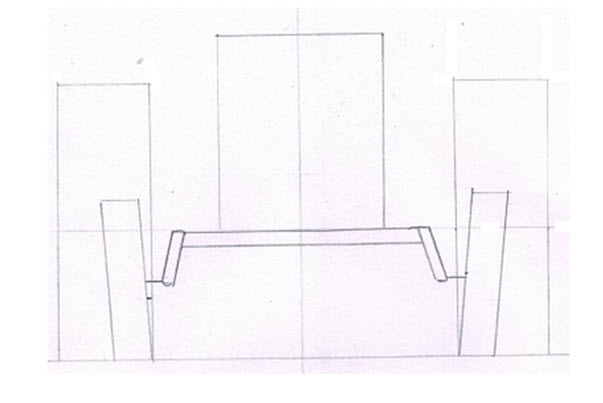
TOE-IN
Front wheels are usually drawn in slightly in front so that the distance between the back-ends (y) in slightly more than the distance between front-ends (x). The different between these distances is called toe in. Wheels are toed-in to offset the tendency for them to roll outward due to camber and to play in the steering linkage.
Toe-in is usually 2-4 mm.
TOE-OUT
When a vehicle takes a turn, the inside wheel moves faster than the outer wheel because the former has to negotiate an are with shorter radius than the latter. This action causes the wheels to out-out on turns because of difference in their turning angles.
STEERING SYSTEM
The function of a steering system is to convert the rotary movement of the steering wheel in driver's hand into the angular turn of the front wheels on road. Further, the steering system should provide mechanical advantage over front wheel steering knuckles, offering driver easy turning of front wheels with minimum effort in any desired direction.
There are two types of steering:
- Mechanical Steering
- Hydraulic Steering
MECHANICAL STEERING (ACKERMAN-TYPE)
When driver turns the steering wheel, motion is transmitted down through the steering tube to the steering gear. The steering tube revolves inside the steering column. The steering gear changes the direction of motion and increase the turning force applied by driver of the steering wheel in accordance with gear ratio. The gear rotates the steering arm (pitman arm) which transfers the motion to the steering knuckles through the steering gear connecting rod, tie-rod and knuckle arms. This type of linkage is called the relay steering linkage.
The king-pin torque (T) required to turn the wheel under a vertical load (W) can be calculated by the following equation:
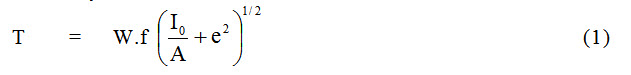
Where,
f = effective friction coefficient
I0 = polar moment of inertia of tire print, m4
e = Kingpin-offse,t m
A = tire print area, m2
This equation assumes a uniform tire print pressure. If the exact shape of the tire print is unknown, an approximation can be made by assuming it to be circular with diameter equal to the nominal tire width, b, then
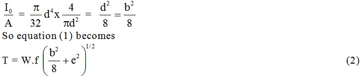
The change in steering torque as a function of king-pin offset is shown by the curve given below:
The curve shows that an optimum king-pin offset e, exists for a minimum value of torque, T. Also the optimum offset varies with the different surface conditions. A small king-pin offset or even centre point steering in which the offset e approaches zero is better suited for heavily loaded tires in loose soil where rolling resistance is high. If the steered wheel is also powered or is equipped with brakes, a small or zero offset is also advisable to reduce feedback of forces into the steering system.
The curve below shows that generally accepted typical effective coefficient of friction for rubber tires on dry concrete as a function of the king-pin offset to tire width ratio.
Importance of wheel alignment
1. Improve Handling: - This helps in controlling the vehicle. Improper handling can be due to vehicle pulling on one side, vibration of the steering wheel.
2. Improves tyre life and performance: - Proper rolling tyre contact on road and prevention of slipping of the tyres due to improper alignment results in better tyre life.
3. Helps in identifying problems: - Improper alignment could be a symptom of something wrong in the vehicle. A check on this can lead to correction in the fault in the vehicle.
4. Ensures Safety: - By keeping the system in order by removing the defective parts, enhances the vehicle systems, especially the suspension system, leading to better safety.
5. Improves fuel efficiency: - By enhancing theperformanceof various systems, leads to better fuel efficiency from the vehicle.
Last modified: Monday, 3 March 2014, 6:15 AM